TM5-6115-634-14&P
NAVFAC P-8-647-14&P
T0-35C2-3-445-14
TM-6115-14&P/1
5-29.
TEST AND REPAIR REMOTE CONTROL UNIT (cont)
m.
Connect ohmmeter across J29D
pins b and d then rotate FREQ
ADJUST (set no. 1) from fully
counter-clockwise to fully
clockwise.
Meter indication
should change smoothly from
O-to-500 ohms.
n.
Repeat step 2.m. above, using
J29D pins f and W.
o.
Use the multimeter to test for
continuity between J29D pins B
and Y, G and H, H and J, n and
p, V and i, N and M, M and L,
and g and k.
p.
If any test step (2.a through
2.o) failed, the unit must be
repaired.
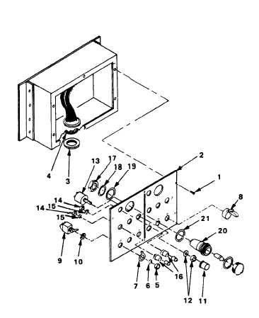
REPAIR
REPAIR CONTROLS AND INDICATORS
a.
Repair by replacing faulty
controls and indicators as
follows:
(1) Remove six screws (1) that
secures the control panel
(2) to the housing.
(2) Remove ring nut (3), from
J29D connector (4) and
carefully push connector
inwards from port.
(3) Remove control panel (2)
and wiring harness from
housing.
b.
Remove ENGINE START/STOP, CON-
TACTOR CLOSE/OPEN and BATTLE-
SHORT ON/OFF switches.
5-55