TM5-6115-634-14&P
NAVFAC P-8-647-14&P
T0-35C2-3-445-14
TM-6115-14&P/1
MAINTENANCE OF SPECIAL RELAY ASSEMBLY
5-25. TEST SPECIAL RELAY ASSEMBLY
This task covers: a. Removal
c. Installation
b. Test
INITIAL SETUP
Tools
Equipment Conditions:
Reference
General Mechanic’s Tool Kit
Para. 4-9 General Instructions.
5180-00-177-7033
TM5-6115-464-34
Solder/Desolder Kit
Remove Static Exciter and Voltage
3439-00-460-7198
Regulator Assembly Para. 5-13.
Multimeter
6625-01-139-2512
Materials/Parts
Special Relay Assembly
97403-13228E1904
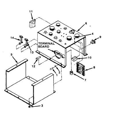
REMOVAL
REMOVE SPECIAL RELAY ASSEMBLY FROM
RELAY TABLE.
a.
Tag and disconnect wiring har-
nesses from special relay
assembly connectors.
b.
Remove six screws (1), lock-
washers (2), nuts (3) and re-
move the special relay
assembly from relay table in
generator set.
c.
Disassemble only as necessary
to test for faulty components.
Remove two screw and captive
d.
washer assemblies (4) and re-
move chassis (5) from special
relay assembly (6).
5-43