TM5-6115-593-34
NAVFAC P-8-631-34
TO-35C2-3-463-2
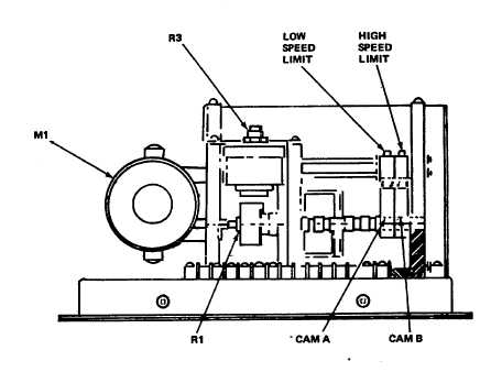
Figure 4-17. Motor-Operated Potentiometers, Cam Adjustment
(b)
Remove
retaining
ring
(10)
friction cover (11) and spring
(13). Elastic stop nut (12) is
accessible for torque increase
or decrease. Clutch assembly
may be removed for torque
adjustment by removing set
screws (10).
(4)
Adjust clutch (16, figure 4-15) to 20 ±5
inch-ounce (0.15 ±0.15 ±0.04 joules).
Add shims if necessary to reduce
looseness between motor shaft and
clutch. Adjust torque with nut as
shown in figure 4-18. Clutch assembly
must be disassembled in accordance
with figure 4-15 as follows:
(a)
With
cover
(3)
removed,
remove motor mounting plate
(17) and motor (9) by removing
two screws (8).
(b)
Remove
retaining
ring
(10)
friction cover (11) and spring
(13). Elastic stop nut (12) is
accessible for torque increase
or decrease. Clutch assembly
may be removed for torque
adjustment by removing set
screws (19).
Figure 4-18. Motor-Operated Potentiometers, Clutch
Adjustment Nut
4-29