TM5-6115-593-34
NAVFAC P-8-631-34
TO-35C2-3-463-2
a. Test.
(1) Check each relay using test circuits
shown in figure 15-8. Energize each
set of relay contacts individually by
applying 24V DC directly to leads.
Check for open or closed contacts (no
continuity or continuity) as indicated in
figure 15-8. Check that each set of
contacts revert (to either closed or open
position) when deenergized. If only
relay fails to either open or close as
indicated, it is defective and must be
replaced.
(2) Check diodes for polarity. A good diode
will read high resistance one way and
low resistance the other way. A
defective diode will read full scale both
ways, or will read infinity (no reading) in
either direction.
(3) Check terminal boards and printed circuit
wiring by repeating steps (1) and (2),
but apply 24V DC to A20 terminals.
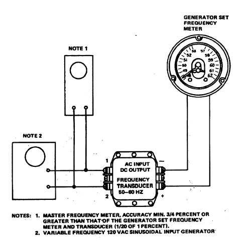
Figure 15-6. Transducer A103, Test Setup
15-8

