TM5-6115-593-34
NAVFAC P-8-631-34
TO-35C2-3-463-2
of engine, taking up all end play, and set
gauge at zero. The crankshaft must move
freely.
(13) Move crankshaft toward rear of engine. The
gauge should indicate 0.006 to 0.013 inch
(0.15 to 0.33 mm) end clearance for a new
engine, or an engine with new crankshaft and
new bearings.
(14) If end clearance is less than stated in step
(13), loosen capscrews slightly and shift
crankshaft toward front of engine, then toward
rear of engine. If capscrews have been
loosened, retighten as described in step (9).
Recheck end clearance.
NOTE
When an engine is being rebuilt,
always bring crankshaft end clearance
to 0.006 to 0.013 inch (0.15 to 0.33 mm)
by using standard new parts or by
using oversize thrust rings and a
reconditioned crankshaft.
(15) Bend in ear of each lockplate (37) against the
main bearing capscrew to lock it in place.
(16) Install and torque main bearing capscrews on
engines to the following values:
(a) Torque all right side capscrews to 70 to
75 foot-pounds (95 to 102 joules).
(b) Torque all left bank side capscrews to 70
to 75 foot-pounds (95 to 102 joules).
(c) Return to right bank and torque side
capscrews to 135 to 145 foot-pounds
(183 to 197 joules).
(d) Return to left bank and torque side
capscrews to 135 to 145 footpounds
(183 to 197 joules).
(e) Breakaway torque is 135 to 190 foot-
pounds (183 to 258 joules) in tightening
direction.
(17) Install camshaft bushings (23, figure 13-50)
using a bushing driver. Make certain that oil
passages between bushings and block oil
holes are properly aligned.
13. 35. INJECTION TIMING. After repair or overhaul,
the engine should be timed as follows:
NOTE
Timing No. 1 cylinder on right and left
bank will accomplish complete engine
timing. Repeat following steps for
each of the two cylinders.
a. Injector push tubes should be installed in their
sockets for timing operation.
b. Check No. 1 cylinder on each bank with injector
timing tool at 19 degrees before top center
firing position.
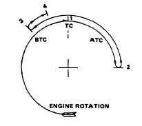
c. Install timing tool in place of injector with one rod
in push tube socket and with other rod resting
on piston. Follow procedures as shown on
figure 13-54 and steps e(1) through e(4), below.
The numbers on the diagram show check points
corresponding to numbered instruction steps.
Figure 13-54. Engine Injection Timing
Procedure Diagram
d. When indicator gauges are set at "0", they must
be near fully
13-105