TM5-6115-593-34
NAVFAC P-8-631-34
TO-35C2-3-463-2
d.
Repair. Repair by replacing any worn or
damaged valves and springs, as determined in
paragraph b and c above.
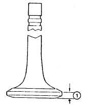
Figure 13-45. Minimum Valve Head Rim Thk.
e.
Installation.
(1) Lubricate valve stem with 140W lubricating
oil and insert valve into valve guide.
(2) Place cylinder head face down on a wooden
bench or protective surface to prevent
marring of milled surface.
(3) Assemble lower valve spring guide over
valve guide.
(4) Assemble springs. Install, if required, up to
1.16 inch (1.59 mm) of spacers to reduce
valve spring length.
(5) Assemble upper valve spring retainer.
Compress valve springs and install new half
collets.
13-29. INTAKE AND EXHAUST VALVE SEATS. Refer
to paragraph 13-27 for procedures covering inspection
and replacement of the intake and exhaust valve seats.
13-30. CYLINDER HEAD. Refer to paragraph 13-27
for
procedures
covering
inspection,
replacement,
overhaul, and rebuilding of the cylinder head.
13-31. VALVE LIFTERS. Refer to paragraph 13-25 for
inspection and replacement of the valve lifters (levers).
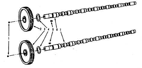
13-32. CAMSHAFT. Refer to figure 13-46 and proceed
as follows:
a.
Removal.
(1) Remove push rods and tappets as specified
in paragraph 13-26.
(2) Remove
gear
cover
as
specified
in
paragraph 13-23.
LEGEND
1.
Plug
5.
Key
2.
Gear
6.
Camshaft
3.
Gear
7.
Camshaft
4.
Washer
Figure 13-46. Camshafts, Exploded View
13-88


