TM5-6115-593-34
NAVFAC P-8-631-34
TO-35C2-3-463-2
CAUTION
Special care must be used to avoid
breaking carbide tips. Sharpen tipped
tools on a diamond-impregnated wheel.
(15) Remove crosshead guides marked for
replacement using a dowel puller.
(16) Using a crosshead guide mandrel, press
new guides into cylinder head to obtain
protrusion of 1.860 to 1.880 inch (47.24 to
47.75 mm).
(17) If crosshead guide bore is worn or
mutilated, install oversized guides as
follows:
(a) Drill guide bore in head to original depth
with a 29/64-inch drill.
(b) Lubricate and ream bore with a 15/32-
inch reamer.
(c) Install
oversized
guide
until
guide
protrusion is 1.860 to 1.880 inches
(47.24 to 47.75 mm).
(18) Remove loose or excessively worn valve
seat inserts by striking insert sharply with a
chisel, causing it to crack and release the
press fit. Remove all inserts if head has
been resurfaced.
CAUTION
Cover the valve seat with a rag to avoid
injury from broken pieces of the seat.
(19) Enlarge counterbore to next oversize using
valve seat insert cutter. Inserts are
available in standard and oversizes as
tabulated in Chapter 1.
NOTE
If head was resurfaced and standard
inserts
are
to
be
used,
deepen
counterbore only.
(20) A valve seat insert tool must be used to
hold and drive cutters.
(21) Cut counterbore 0.006 to 0.010 inch (0.15
to 0.25 mm) deeper than insert thickness to
permit peening of head to hold insert. It is
important to allow cutter to dwell for
several revolutions upon reaching proper
depth in order to ensure a perfectly flat
surface at the bottom for the insert to seat
on.
(22) Install valve seat insert and peen around
insert at least five places with a 1/4 inch
(6.35 mm) diameter round end punch.
(23) After
checking
condition
of
grinding
equipment, grind valve seats holding
seating
motor
as
nearly
vertical
as
possible.
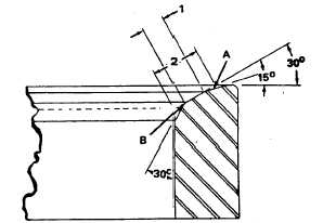
(24) Check valve seat which should be 1/16 to
1/8 inch (0.159 to 3.17 mm).
(a) If seating area (2, figure 13-44) is wider
than 1/8 inch (3.175 mm) maximum,
stock can be removed from points "A"
and "B" with specially dressed valve
seat grinder stones.
(b) Narrowing should not extend beyond
chamfer on seat insert. Chamfer
provides for peening metal.
Figure 13-44. Valve Seat Insert, Cross Sections
(25) Dress wheel for final finish.
13-84