TM5-6115-593-34
NAVFAC P-8-631-34
TO-35C2-3-463-2
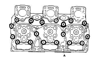
Figure 13-42. Head Capscrew Tightening Sequence
c.
Inspection.
(1) Check valve seats and injector sleeve for
cracks. Discard cylinder head if cracked.
(2) Check all valve springs for damage.
(3) Check for signs of metal erosion around
water holes.
(4) Check cylinder head for worn or uneven
surface at point of contact with gasket.
(5) Examine fuse plug for signs of overheating.
If plug shows signs of overheating, check
for further damage and replace if necessary.
d.
Repair.
(1) Replace any damaged valve springs.
(2) Insert sleeves into water holes that have
become enlarged due to metal erosion.
Refer to paragraph 13-27 f.
(3) Resurface head surface that is deeply
scratched or worn. Rework valve seat insert
counterbore by removing amount of stock
equal
to
that
removed
during
head
resurfacing operations. Refer to paragraph
13-27 f.
(4) If exhaust ports are not flat, resurface
exhaust ports. Exhaust ports should not be
more than 0.003 inch (0.08 mm).
e.
Overhaul.
(1) Using a valve spring compressor, compress
valve springs (6), remove half collets (3),
retainers (5), spring (6), valve spring guides
(7), and guides (9).
NOTE
Perform the necessary tests to determine
the extent of overhaul or the scope of
rebuilding required to the cylinder head.
(2) Hydrostatic Testing
(a) Install injector sleeve holding tool or a
scrap injector assembly in each injector
sleeve. Tighten tool or injector hold-
down capscrews to 10 to 12 foot-pounds
(14 to 16 joules) torque to seal lower
end of injector sleeve and place cylinder
head
in
the
hydrostatic
tester
or
equivalent.
WARNING
OVERHEAD
OPERATIONS
HAVE
INHERENT HAZARDS THAT CANNOT BE
MECHANICALLY SAFEGUARDED. HARD
HATS
AND
SAFETY
SHOES
ARE
REQUIRED.
(b) Use hoist to position head and tester
over
13-80