TM5-6115-593-34
NAVFAC P-8-631-34
TO-35C2-3-463-2
drive speed gradually and observe that the
contacts close in the 290 to 310 range.
(5)
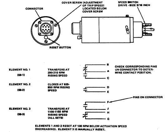
Connect ohmmeter leads across pins D and E
and verify an open circuit. Increase drive speed
and observe that elements S9-2 (contacts D and
E) closes in the speed range of 590 to 610 rpm.
Gradually reduce speed to 490 minimum rpm.
Observe that element S9-2 resets to the
condition shown in figure 13-2.
(6)
Connect ohmmeter across pins H and G
connector and verify a closed circuit. Increase
drive speed gradually. The contacts should
open at a speed of 1100 to 1150 rpm. Hold
drive speed and read contacts F and J. Meter
should indicate a closed circuit. Reduce drive
speed to less than 1000 rpm, press the manual
reset switch and observe with the meter that
element S9-3 contacts reset to the condition
shown in figure 13-2.
(7)
To obtain the required performance
characteristics during tests (3) through (6),
adjustments can be made. By loosening screws
(1, figure 13-1) and rotating the cap and cover
assembly relative to the body assembly, the trip
points of all those elements can be raised or
lowered. In addition, the trip speed of each
individual element can be raised or lowered by
removing cover screws as shown in figure 13-2
and turning appropriate set screw located
beneath cover screws with a 1/16 inch Allen
wrench.
Figure 13-2. Speed Switch Sensitivity Tests (Mechanical Type Switch) (Code “A")
13-3