TM5-6115-593-34
NAVFAC P-8-631-34
TO-35C2-3-463-2
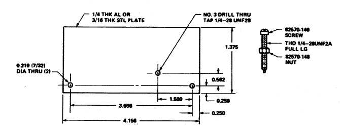
Figure 12-1. Speed Setting Adapter Plate
with the shaft hole in the droop lever (33).
(7)
Close needle valve (92) 1/4 to 1/2
turn from bottoming to stabilize unit.
(8)
Check governor section for leaks,
hunting, drifting and oil pressure.
c.
Governor Needle Valve Setting. Eliminate any air
trapped in the actuator passages if not already done
in the preliminary set-up. With the governor
controlling, open needle valve (92) until the unit hunts
or surges. After 2 or 3 minutes, gradually close the
needle valve until the speed just settles out. Closing
the needle valve further than necessary makes the
unit slow to return to set speed after a load change.
Never close the needle valve tight. Test the unit by
manually disturbing the speed. Only a small
overshoot or undershoot should occur before the unit
returns to its steady-state speed. The actuator has no
needle valve adjustment.
d. Speed Droop Adjustment. Speed droop is adjustable
internally. The speed droop bracket (32) is clamped
to the speed droop lever with a setscrew. A pin on
the droop bracket carries the floating lever (19).
When this pin is aligned with the droop lever shaft the
droop will be
zero. Move the speed droop bracket towards the ballhead
to increase droop. Speed droop is normally set in the
range of 3 to 6 percent.
e.
Centering Pilot Valve Plunger.
(1)
Adjust speed adjusting screw until
governor is approximately 5 percent above
steady-state speed.
(2)
Disconnect test stand linkage
from terminal shaft.
(3)
Back out actuator pilot valve
plunger screw (63) 1-1/2 to 1-3/4 turns after
bottoming very carefully against spring.
Use a 7/64 inch (2.8mm) hex wrench.
(4)
Set test circuit (figure 12-2) to
OFF and connect to transducer plug on
actuator case.
(5)
Connect a 9 VDC power source
to test circuit. Set test circuit to CENTER.
(6)
Adjust test circuit potentiometer
to 400 ma then set switch to OFF.
(7)
Adjust spring seat screw (56) with
a 1/8 inch (3.2 mm) hex wrench until
terminal shaft rotates approximately to its
midpoint of travel. Turn spring seat screw
(56) clockwise to move terminal
12-2


