TM 5-6115-593-12
TO 35C2-3-463-1
Section II. OPERATION OF AUXILIARY MATERIAL USED IN CONJUNCTION
WITH THE EQUIPMENT
2-8. GENERAL. This section provides step-by-step
procedures with supporting illustrations for operating the
generator set in conjunction with the auxiliary housing
kit, the remote control module and cable, and the
automatic control module.
2-9. OPERATION WITH THE HOUSING KIT. The
auxiliary housing kit encloses the top, sides, and ends of
the generator set and is removable to provide access for
overhaul or replacement of major components of the
generator set. The housing is attached to the base
assembly and the support frame assembly to provide a
rain-proof enclosure, and prevent rain, snow, or sand
from entering the interior of the housing. The housing
doors allow access to the inside of the generator set.
The shutter assembly at the radiator end of the
generator set is automatically controlled and opens as
necessary to facilitate air circulation. Installation of the
housing kit extends the operational capability of the
generator set down to temperatures from 40°F to -25°F
(4.4°C to -32°C). Preparation procedures for starting
the generator set with the housing kit installed are given
in figure 2-9.
STEP 1.
CHECK LUBRICATING AND COOLANT LELS.
STEP 2.
CHECK AIR BOX DAMPER POSITION AND RESET MANUALLY TO OPEN IF P E. S FIG. 2-5 SHEET 1.
STEP 3.
CHECK BATTERY TERMINALS, S (-) TO GROUND.
STEP 4.
PLACE 24V DC CONTROL CIRCUIT BREAKER TO ON POSITION ON GENERATOR PANEL.
STEP 5.
ENSURE MAINTENANCE SWITCH IS IN OPERATION POSITION ON AC-DC CONTROL PANEL.
STEP 6.
CHECK FUEL LEVEL AND SIDE DOOR SHUTTER OPERATION BY PLACING BATTLE SHORT SWITCH
IN THE ON POSITION ON GENERATOR PANEL AND THEN THE MASTER SWITCH IN START
POSITION ON ENGINE PANEL.
STEP 7.
RETURN MASTER SWITCH TO STOP AND THEN THE BATTLE SHORT SWITCH TO OFF.
STEP 8.
CHECK ENG FAULT INDICATORS BY PLACING ANNUNCIATOR TEST SWITCH IN TEST POSITION ON
GENERAL PANEL.. IF NONE OF THE LIGHTS ARE ON AFTER BEING TESTED PROCEED WITH THE
NEXT STEP. IF A LIGHT DOES COME ON, CORRECT THE INDICATED FAULT BEFORE
PROCEEDING.
STEP 9.
CHECK VOLTAGE AND FREQUENCY OF THE LOAD AGAINST THE VOLTAGE AND FREQUENCY
CONNECTION OF THE SET.
STEP 10.
ENSURE THAT THE SHUTTERS ON THE RADIATOR END OF THE SET ARE NOT MANUALLY LOCKED
OPEN.
STEP 11.
CLOSE ALL DOORS EXCEPT CONTROL BOX END.
STEP 12.
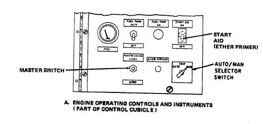
PLACE AUTO/TRIP/MAN SELECTOR SWITCH IN MAN POSITION.
Figure 2-9. Preparation for Starting with Housing
Kit Installed (Sheet 1 of 3)
2-20