TM5-6115-585-34
NAVFAC P-8-262-12
TO-35C2-3-455-2
TM-05684C-34
If pin is excessively loose, install a new piston and
pin assembly.
NOTE
Piston and pins are matched sets and are not
procured separately.
(3) Rings. Place each piston ring into its cylinder
bore and using a feeler gauge measure gap dimen-
sions. Gap is shown in Table l-2 If gap is under 0.010
inch, file
(a)
(b)
(c)
as follows:
Place file in vise.
Grasp piston ring in both hands.
Insert file into ring gap and move ring down
the entire length of file. Be sure-to apply equal-pres-
sure on the ring.
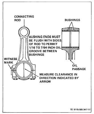
(4) Connecting Rods (see figure 7-17). Clean con-
necting rods and check each for defects. Check con-
necting rod bushings for proper clearance with piston
pin. Clearance is given in Table 1-2. If bushings (13,
figure 7-14) are excessively worn, press them out and
install one new bushing from each side of bushing
bore. Press new bushings only until flush with sides
of rod to leave 1/16 to 7/64 inch oil groove in center.
Ream bushing I.D. to obtain the proper clearance.
Check bore in connecting rod. Bore must be open.
Check connecting rod alignment on a standard align-
(5) Connecting Rod Bearings (see figure 7- 17).
Inspect connecting rod bearings for burrs, breaks,
pits and wear. Measure clearance between bearings
and crankshaft journal. See Table 1-2 for clearance. If
necessary, replace with new standard or undersize
precision bearings.
e. Assembly (see figure 7-14).
NOTE
The piston witness mark (notch) must face
front of engine and rod witness marks (num-
bers) must face toward camshaft side of en-
gine.
(1) Install connecting rods (12, figure 7- 14) on
each piston (7) with pins (6) and retaining rings (5).
If new bushings (13) were installed, check to see that
ends are flush with the connecting rod (12) to provide
for oil recess in the center.
(2) Install rings and oil ring expander (1, 2,3 and
4) on each piston (7). Compression rings will be
marked TOP or identified in some other manner.
Place this mark toward the closed end of piston.
Space ring gaps 1/4 of the way around piston from
one another. No gap should be in line with piston pin.
Oil the rings (1, 2 and 4) and pistons (7).
NOTE
ment fixture.
When installing old bearings make sure they
are installed in the same position they were
removed from.
Figure 7-17. Connecting Rod and Bushings
(3) Position a bearing half (11) in connecting rod
(12) and cap (10). Be sure there is no dirt under bear-
ing. This could cause high spots and early bearing
failure.
f. Install,
(1) Hone cylinder walls. Clean and oil the cylin-
der walls. Install each piston in proper cylinder using
a suitable installer. Each piston assembly should be
installed with notch on piston toward front of engine.
The notch on the circumference of the closed end of
the piston should be located closest to front of engine.
(2) Position each connecting rod on crankshaft
and oil the journal and install rod cap with bearing
half. When installing rod cap, position so raised wit-
ness mark on the forging matches the mark on con-
necting rod. See figures 7-17 and 7-18. The piston
witness mark should face front and rod witness marks
toward camshaft side of engine.
(3) Tighten capscrews to specified torque. See
table 1-1.
(4) Turn engine over by hand to see that all
bearings are free.
7-18