TM5-6115-585-34
NAVFAC P-8-623-34
TO-35C2-3-455-2
TM-05684C/05685B-34
7-8.
a.
BATTERY CHARGE ALTERNATOR.
(2) With generator running, disconnect batteries
leaving 12 ohm resistor load in circuit to generator.
Inspect (see figure 7-7).
The alternator should provide a dc voltage between
(1) Refer to Operator and Organizational
Maintenance Manual and remove blower housing.
(2) Check stator wiring and voltage regulator
wiring for loose connections or shorts. Check fuse F 1
(16).
b. Test on Equipment.
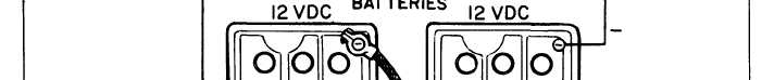
(1) Load the batteries with a 12 ohm, 200 watt
resistor (see figure 7-8). Run the set at rated fre-
quency. The charge rate should be between 6.5 and
24 and 28.5 volts. -
c. Removal.
(1) Rotor.
R e f e r t o O p e r a t o r a nd
Organizational Maintenance Manual and remove the
blower housing. Remove blower wheel assembly (4,
figure 7-7) per paragraph 7-7. Remove rotor mounting
screws (9) and lockwashers (10) attaching rotor(11) to
blower wheel (4) and remove rotor (11).
(2) Stator. Disconnect stator leads (14, figure
7-7) from terminal block on engine back plate. Re -
move wire clamp from oil filter casting. Remove
screws (12) and lockwashers (13) attaching stator (15)
10 amperes.
to engine and remove stator (15).
Figure 7-8. Resistively Loading the Batteries
7-8
Change 2