e. Replace. Using screws (13, figure 7-2), lock-
washers (14), and nuts (15), attach governor control
bracket (12) to engine back plate. Attach speed control
cable (11) to governor arm (3) with pin (6) and cotter
pin (5). Attach governor arm (3) and governor linkage
(1) between governor and fuel injection pump (2). If
new ball joints are used on linkage, position the new
joints to obtain the same length or 1/32 inch more (1
turn = 1/32 inch) than the old linkage. If old linkage
length is not available, position new ball joints about
midway on each end linkage, then lengthen 1/8 inch.
DO not overspeed engine for
moment.
more than a
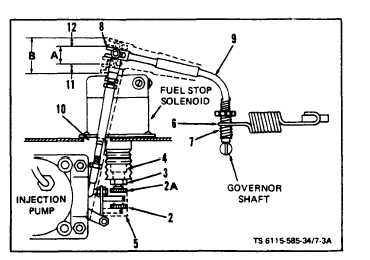
f. Preliminary Linkage Adjustment (figure 7-3.1).
The following adjustments shall be made before
starting the engine if the linkage was replaced.
(1) With link (1) compressed, adjust length be-
tween ball joints to 5-1/2 in.
(2) Set solenoid bumper screw to shut off posi-
tion, dotted line (2), by loosening locknut (3) on sole-
noid plunger (4). With plunger down, adjust bumper
screw to push control unit post down, dotted line (5),
to maximum shutoff position.
(3) Hook governor spring (6) in the mid-range of
sensitivity ratchet (7).
(4) Manually move governor arm and linkage to
check for interference.
(5) Adjust position of upper ball joint in slot
(8) on governor arm (9) so link (1) does not bind
against fuel stop solenoid or hole (10). A slight con-
tact of link to bottom of solenoid is permissible but
only at shut down. The fuel control unit should move
up to position (2A) when solenoid is energized with
start switch.
g. Final Linkage Adjustment. Perform the follow-
ing steps to establish governor overshoot and under-
shoot, balancing external linkage movements within
the range of governor internal parts.
(1) Start engine and, with no load, adjust speed
control for rated frequency.
(2) Push linkage downward (11) about 1/4 in.
with light finger pressure. If the linkage appears to
reach governor internal travel limit (higher pressure
is felt), stop engine and lengthen linkage as required.
(3) Apply rated load and adjust speed control
for rated frequency.
CAUTION
Shortening the linkage too much in the follow-
ing step will prevent no-load speed control,
or may cause a runaway engine.
h. Speed Droop Adjustment (figure 7-3.1 ). Droop
between no load and rated load is adjusted by ro-
tating ratchet (7).
Clockwise rotation decreases
droop; counterclockwise rotation increases droop.
Start engine and with no load, adjust speed control
for rated frequency. While observing the set fre-
TM5-6115-585-34
NAVFAC P-8-623-34
TO-35C2-3-455-2
TM-05684C/05685B-34
quency meter, change from no load to full load several times. Adjust to
minimum droop obtainable. Repeat as required. On ASK equipped gen-
erators, refer to Operator and Organizational Maintenance Manual and
replace right panel assembly.
Figure 7-3.1. Governor Linkage Adjustment
NOT E
If droop is too small, hunting (periodic fre-
quency swings) will occur when changing from
no load to full range because the governor
will be too sensitive.
7-4. FLYWHEEL AND RING GEAR ASSEMBLY
a. Removal (see figure 7-3).
(1) Remove engine from set per paragraph 2-9.
(2) Remove timing pointer (10, figure 7-3) by re-
moving screws (11).
(3) The flywheel (1) is a tapered fit on the
crankshaft (2). Remove flywheel mounting screw (3)
and washer (4). Support and remove flywheel and ring
gear assembly by using a two pronged wheel puller
inserted through the slots provided in the flywheel.
b. Clean and Inspect. Clean the flywheel and ring
gear assembly (1) using solvent. Check the ring gear
for broken or worn teeth.
c. Install. Replacement flyheels are supplied with
timing marks already stamped in place. The engine
must still be timed properly to this timing mark. The
only accurate method of determining the port closing
point is to measure piston travel. This is a critical
measurement and should be done only with accurate,
dependable equipment Mount flywheel keying
properly and tighten in place using screw (3) and
washer (4), (figure 7-3). With the flywheel mounted,
rotate flywheel counterclockwise until Number 1
cylinder is on its compression stroke, which follows
the closing of its intake valve. Remove the exhaust
rocker arm (3, figure 7-9), exhaust valve rotator (1,
figure 7-11). valve looks (2), spring retainer (3) and
spring (5), using fabricated tool (see figure 7-10).
Allow exhaust valve to drop down onto top of piston.
Rotate flywheel counterclockwise until piston is at
Change 6
7-5