TM5-6115-585-34
NAVFAC P-8-262-12
TO-35C2-3-455-2
TM-05684C/05685B-M
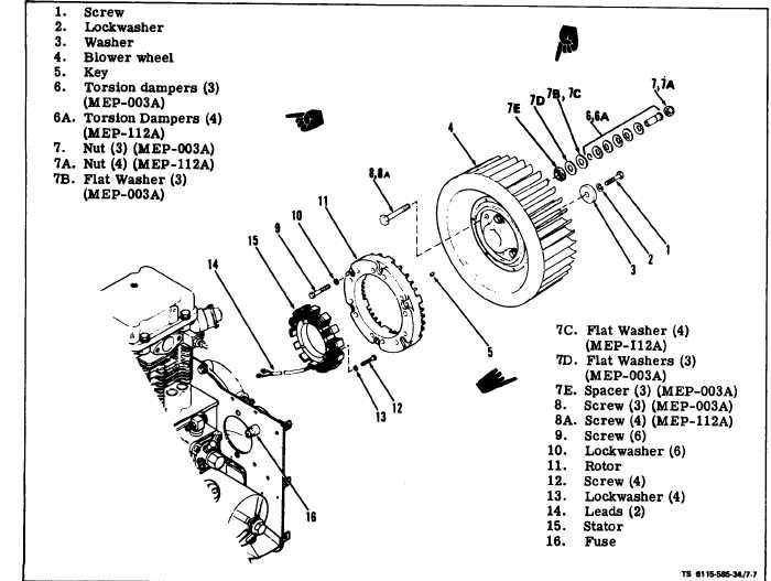
Figure 7-7. Battery Charge Alternator and Blower Wheel
(1) Plug the oil cooler outlet using suitable plug.
NOTE
(2) Connect the oil cooler in suggested test set-
up (see figure 7-6).
Observe the arrangement of the conical
washers in the torsion damper assemblies.
(3) Apply 25 psi air pressure to the oil cooler.
These washers must remain ‘in the same ar-
(4) Close the valve and monitor the pressure. A
rangement of the originally assembled set or
drop in air pressure indicates a leak in the oil cooler.
the function of the dampers will be impaired.
7-7. BLOWER WHEEL ASSEMBLY.
a. Inspect (see figure 7-7).
(1) Refer to Operator and Organizational
Maintenance Manual and remove blower housing.
(2) Check blower wheel (4) for cracks or broken
fins. Check for free play between blower wheel and
hub. Replace torsion damper assemblies (6) if free
play is present.
b. Removal. Remove screw (l), lockwasher (2) and
washer (3), attaching blower wheel to crankshaft. Use
two 5/16-24 screws in blower hub and a suitable
c. Repair. Blower wheel and hub are a balanced
unit and should not be disassembled. To replace tor-
sion damper assemblies, remove screws, nuts, and
replace torsional dampers and reuse flat washers
and spacers as required for that type set. Torque
screws 28-30 ft-lb.
d. Install.
(1) Mount blower wheel assembly to crankshaft
using screw (l), lockwasher (2) and washer (3). Torque
screw (1) to 65-70 ft-lb.
(2) Refer to Operator and Organizational
puller to remove blower wheel (4) and key (5).
Maintenance Manual and install blower-housing.
Change 2 7-7