TM 5-6115-584-34
NAVFAC P-8-622-34
TO-35C2-3-456-2
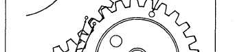
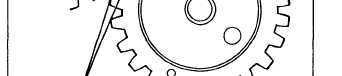
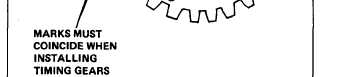
Figure 7-26. Crankshaft and Camshaft
Gear Timing Marks
(12) Refer to Operator and Organizational
Maintenance Manual and install rocker arm covers.
(13) Refer to paragraph 2-9 and install engine.
(14) Refer to Operator and Organizational
Maintenance Manual and install blower housing.
7-17. CRANKSHAFT AND BEARINGS=
a. Removal (see figure 7-15).
(1) Refer to Operator and Organizational
Maintenance Manual and remove blower housing.
(2) Refer to paragraph 2-9 and remove engine.
(3) Refer to paragraph 7-7 and remove blower
wheel.
(4) Refer to paragraph 7-8 and remove alternator
stator.
(5) Refer to paragraph 7-14 and remove gear
cover.
(6) Refer to paragraph
heads.
(7) Refer to paragraph
flywheel and housing.
7-9 and remove cylinder
7-4 and 7-5 and remove
TM-0568C-34
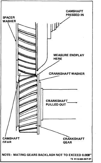
Figure 7-27. Timing Gear Backlash
(8) Refer to paragraph 7-10 and remove oil base.
(9) Refer to paragraph 7-11 and remove oil pump
cup assembly.
(10) Remove lock ring (14) and retaining washer
(15) in front of crankshaft gear (16).
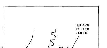
(11) Pull off crankshaft gear. It has 2-1/4-20 UNC
tapped holes for attaching a gear pulling ring (see
figure 7-28). Use care not to damage teeth if gear is
to be re-used. Remove woodruff keys (25, figure 7-15).
(12) Refer to paragraph 7-10 and remove connec-
ting rod and piston assemblies.
(13) Remcve rear bearing plate (18, figure 7-15)
from crankcase. Remove gasket (22) and shims (23).
7-27