TM 5-6115-584-34
NAVFAC P-8-622-34
TO-35C2-3-456-2
TM-0568C-34
cover (6) to crankcase. Tape crankshaft keyway to
prevent damage to seal. To loosen gear cover, tap it
with a soft hammer. Remove gasket (7).
c. Disassemble and Inspect.
(1) Governor Shaft (see figure 7-22). The gover-
nor shaft (5) is supported by two sets of needle bear-
ings (7). To remove shaft, remove retainer (1) and
yoke (2) and pull shaft (5) from gear cover (13). If
shaft is binding, clean bearings, if loose, replace
bearings. To remove larger bearing (7) drive bearing
oil seal (11) out from the outside of gear cover. Re-
move smaller bearing (8) with bearing puller. Press
new bearings and oil seal into place.
(2) Gear Cover Oil Seal (see figure 7-22). Re-
place oil seal if damaged or worn. Drive old seal
(11) out from inside gear cover (13). Lay cover on a
board so seal boss is supported. Insert new seal from
inside with rubber lip and closed case toward outside
of gear cover and drive it flush with outside surface.
d. Reassemble.
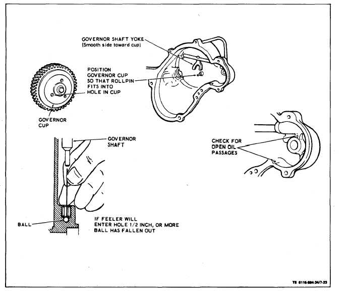
(1) Work governor shaft to check for binding and
see that governor-shaft-end-thrust ball is in place
(see figure 7-23).
(2) Turn governor yoke so smooth side (convex
surface) is toward governor cup (12, figure 7-22) on
camshaft.
(3) Turn governor cup so the stop pin (figure 7-23)
in the gear cover will fit into one of the holes in cup
surface. Measure the distance from end of roll pin to
mounting face of the cover. It should be 25/32 inch.
If it is not, replace pin. Pin should be positioned with
open end facing crankshaft seal.
Figure 7-23. Gear Cover Inspection
7-24