TM 5-6115-545-34
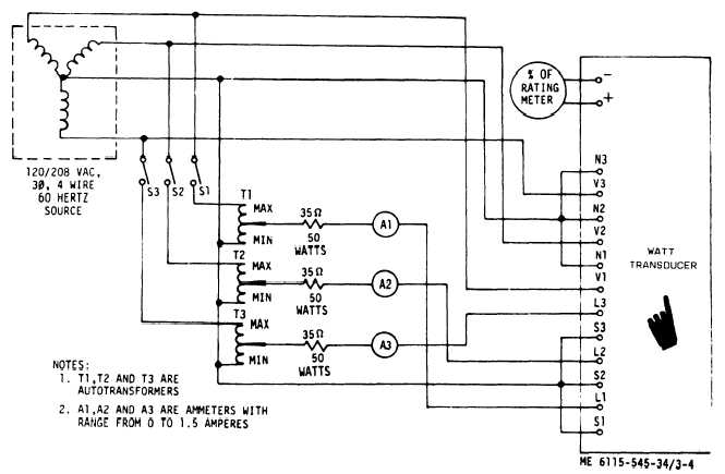
Figure 3-4. Control Cubicle Transducer, Test Setup
3-9. Frequency Meter and Transducer Test.
To test the frequency meter and transducer of the control
cubicle, proceed as follows:
NOTE
3-10. Control Box Relay Testing.
To test the control box relay assembly of the control cubicle
(see figure l-l) and proceed as follows:
CAUTION
The frequency meter and transducer are a
matched set and must be tested as a set.
a. Connect a variable frequency 120 Vac sinusoidal input
—
to the ac side of the frequency transducer,
b. Connect a master frequency meter across the input.
The master frequency meter shall have inaccuracy of a
minimum of 3/4% or greater of the set frequency meter and
transducer (l/20 of l percent).
c. Vary the frequency from lowest scale reading to full
scale reading.
d. The error at any point infrequency meter shall not be
greater than l percent.
e. If the above requirements are not satisfied, replace
both the frequency meter and transducer.
When applying the 120 Vac to control box relay
assembly terminals, insure correct placement of
power supply leads. Damage to other com-
ponents could result if leads are inadvertently
misplaced.
a. With no power applied, check continuity across follow-
ing terminals of the control box relay assembly: terminals
10 and 11; 5 and 6; and 1 and 3 (fig. l-l).
b. Apply a dc voltage of 24 volts to terminals 2 and 8.
The normally open contacts between terminals 7 and 9, and
the normally closed contact between terminals 1 and 3
should transfer (fig. l-l).
c. Apply an ac voltage from 50 to 80 volts, 50/60 Hz or
400 Hz to terminals 4 and 12. The normally open contacts
between terminals 4 and 6, and terminals 10 and 12 and the
normally closed contacts between terminals 5 and 6, and
terminals 10 and 11 should transfer (fig. l-l).
3-6
Change 8