TM 5-6115-465-34
TO35C2-3-446-2
NAVFAC P-8-625-34
TM06858B/06859D-34
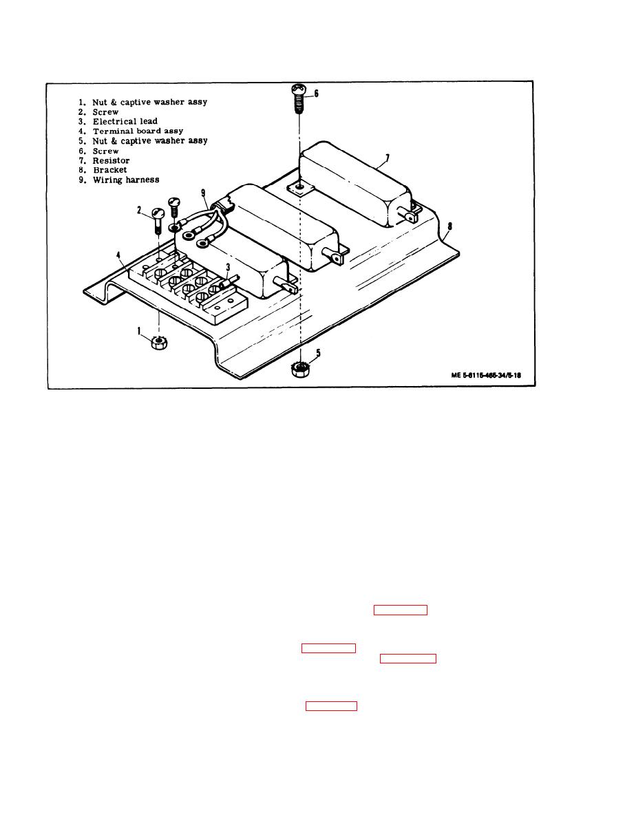
Tactical Relay Resistor Assembly, Exploded View
Figure 5-18.
(13) Using an ohmmeter, test potentiometer
(4) Inspect protective caps for cracks, ex-
as follows:
cessive wear, broken chain and other damage.
(a) Connect ohmmeter leads between cen-
(5) Inspect components of DC relay assembly
ter terminal and either outer terminal.
for cracks, burns, corrosion, and evidence of short-
ing or overheating.
(b) Slowly, at an even rate, rotate adjust-
ment from full counter clockwise to full clockwise
(6) Inspect instrument shunt for turns, corro-
position.
sion, and evidence of shorting.
(c) Ohmmeter indication shall change at an
(7) Inspect special current transformer for
even rate from O to 12 ohms.
corroded terminals and burns or other evidence of
shorting.
(d) Replace potentiometer if ohmmeter in-
dicates discontinuity at any point or if rate of change
(8) Inspect cranking relay K3 for cracked cas-
is erratic.
ing, corroded terminals, and evidence of shorting.
(14) Test wiring harness assembly wires for
(9) Inspect terminal boards for cracks, burns,
continuity using figure 5-20 as a guide.
corroded terminals and terminal jumpers and other
damage.
(15) If wiring, wiring harness has sustained
damage and requires repair or rebuild, refer to
(10) Inspect resistor for burns, corroded ter-
minals and other damage.
requirements and Appendix A for detailed soldering
and replacement procedures.
(11 ) Inspect chassis and cover for cracks,
warping, and illegible markings.
(16) Test dc relay assembly as follows:
(a) Apply 24 Vdc to terminals 6 and 15
(12) Check all threads for crossing, stripping,
and peening.
5-26


