
TM 5-6115-465-34
TO35C2-3-446-2
NAVFAC P-8-625-34
TM06858B/06859D-34
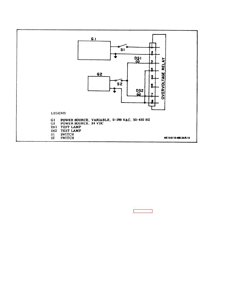
Figure 5-14.
Overvoltage Relay Test Circuit
(b) Activate power source G 1 and adjust
(i) Repeat step (h) for frequencies of 60,
voltage to 120 Vac at 50 Hz.
70 and 100 Hz.
(c) Activate power source G2 and close
(j) Set output frequency of power source
switch S2.
Gl to 350 Hz. Increase output voltage to 151 Volts ac.
DS1 shall extinguish and DS2 shall illuminate. Mom-
entarily open switch S1 and allow relay to reset.
(d) Test lamp DSl shall illuminate and
test lamp DS2 shall remain extinguished.
(k) Repeat step (j) for frequencies of 400
(e) Vary frequency output of power source
and 450 Hz.
Gl from 50 to 450 Hz. There shall be no change in
test lamp illumination.
(11) Test short circuit relay as follows:
(f) Slowly increase output voltage of power
(a) Install short circuit relay in test cir-
source Gl to 149 Vac. Vary frequency from 350 to
cuit shown in figure 5-15.
450 Hz. DS1 shall remain illuminated and DS2 shall
extinguish.
(b) Activate power sources G1 ad G2.
(c) Place switch S2 in the A position and
(g) Slowly increase output voltage of
power source G 1 to 154 Vat. Vary output frequency
close S1.
from 50 to 100 Hz. DSl shall remain illuminated and
DS2 shall remain extinguished.
(d) Slowly increase output voltage of power
source G1. Test lamp DSl shall illuminate.
(h) Set output frequency of power source
G1 to 50 Hz. Slowly increase output voltage to 156
(e) Observe voltmeter V1 while continuing
volts. DS1 shall extinguish and DS2 shall illuminate.
to increase voltage. At a voltage of 24 1 Vac, test
Momentarily open switch S1 and allow relay to reset.
lamp DSl shall extinguish and DS2 shall illuminate.
5-22
