TM 5-6115465-34
TO 35C23446-2
NAVFACP-8-625-34
TM06858B/06859D-34
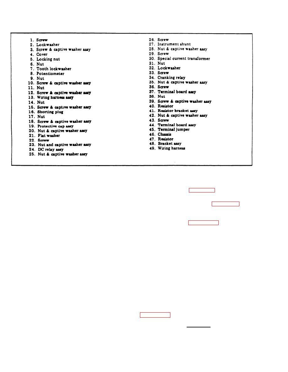
Figure 5-19. Special Relay Assembly, Exploded View (Sheet 2 of 2)
(m) Check resistors R3, R6, and R9 for .
(b) Use an ohmmeter to check for con-
correct values given in figure 5-21.
tinuity across terminals 5 and 17.
( c ) Check for open circuit across ter-
( 1 7 ) Replace defective dc relay assembly
minals 4 and 16.
component (items 1 through 21, figure 5-22).
( d ) Install a jumper between terminals
(18) If any dc relay assembly component
9and6.
must be replaced or encapsulating coating repaired
( e ) Apply 24 Vdc to terminals 12 and
o r replaced, refer to Appendix A references for
15 with 12 positive.
d e t a i l e d procedures. Repair/replace encapsulating
( f ) Check for continuity between ter-
by applying a 0.007 inch (rein) coating of poly-
m i n a l s 5 and 17 and for open circuit between
urethane resin (Scotchcast 221, Minnesota Mining
terminals 4 and 16.
and Mfg. Co. or equal).
( g ) Install a jumper between terminals
(19) Replace any damaged or defective parts.
23 and 6.
d . Installation. Install special relay assembly
( h ) Apply 24 Vdc to terminals 21 and
in reverse order of removal procedures.
15 with 21 positive.
( i ) Check for continuity between ter-
5-12. PRECISE RELAY ASSEMBLY
m i n a l s 5 and 17 and for open circuit terminals
4 and 16.
e. Manufacture. To manufacture the plug, chain
assembly use the connector, plug, electrical NSN
( j ) Apply 24 Vdc to terminals 13 and
(96906)
CAGE/PN
5935-00-548-1529,
15.
MS3456W24-28P.
A l s o use the wire, electrical
( k ) Check for continuity between ter-
CAGE/PN (81349)
NSN 6145-00-578-6605,
minals 1 and 14 and between terminals 2 and 15.
M5086/2-16-9.
C o n n e c t pin (H) to pin (L) per
Check for open circuit between terminals 3 and 15.
(1) Apply 120 Vdc to terminals 18 and
CAUTION
22 with 22 positive. Use an ohmmeter check for
D o not attempt to perform mainten-
resistance of 2500 ohms between terminals 19 and
20 and. 7 and 8.
ance on the precise relay assembly while
the generator is operating. Severe elec-
t r i c a l s h o c k m a y r e s u l t from failure
5-28
Change 9
to observe this warning.


