TM 5-6115-465-34
T035C2-3-446-2
NAVFAC P-8-625-34
TM06858B/06859D-34
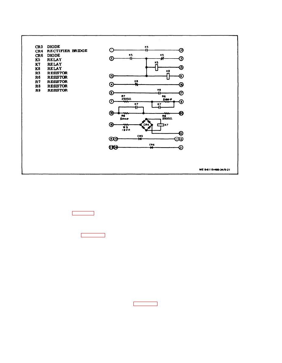
Figure 5-21.
DC Relay Assembly Schematic Diagram
(2) Visually inspect cover and chassis for
a.
Removal.
cracks, corrosion, warping, defective paint and
illegible markings.
(1) Disconnect electrical connectors to pre-
cise relay assembly.
(3) Inspect wiring harness for damaged wires
and connectors for bent or broken connector pins and
(2) Remove screws (1, figure 5-23) and lock-
burned areas indicating shorts.
washers (2) to remove precise relay assembly from
generator set.
(4) Inspect switch (50/60 Hz only) for cracked
casing, burro, corroded terminals and other damage.
b. Disassembly. Disassemble precise relay
assembly (items 3 through 33, figure 5-23) only as
(5) Inspect relays for cracked casing, corro-
required to clean, inspect, test, or replace parts.
ded terminals, and evidence of shorting or other
damage.
NOTE
(6) Inspect resistors and capacitors of elec-
tronic components assembly for insecure mounting
Switch and attaching hardware (items 21
and burns or other evidence of shorting.
through 24) are found only on the 50/60
Hz precise relay assembly.
(7) Inspect terminal board assembly for cracks,
c.
corroded terminals, damaged terminal jumpers and
Cleaning, Inspection, and Repair.
evidence of shorting.
(1) Clean precise relay assembly with filter-
(8) Test under voltage relay as follows:
ed compressed air and a soft bristle brush. If neces-
sary, caked deposits may be removed with a clean,
lint-free cloth moistened with an approved solvent.
(a) Install relay in test circuit shown in
Dry thoroughly after cleaning with solvent.
5-32


