TM5-6115-465-34
TO 35 C2-3446-2
NAVFACP-8-625-34
TM 06858 B/06859D-34
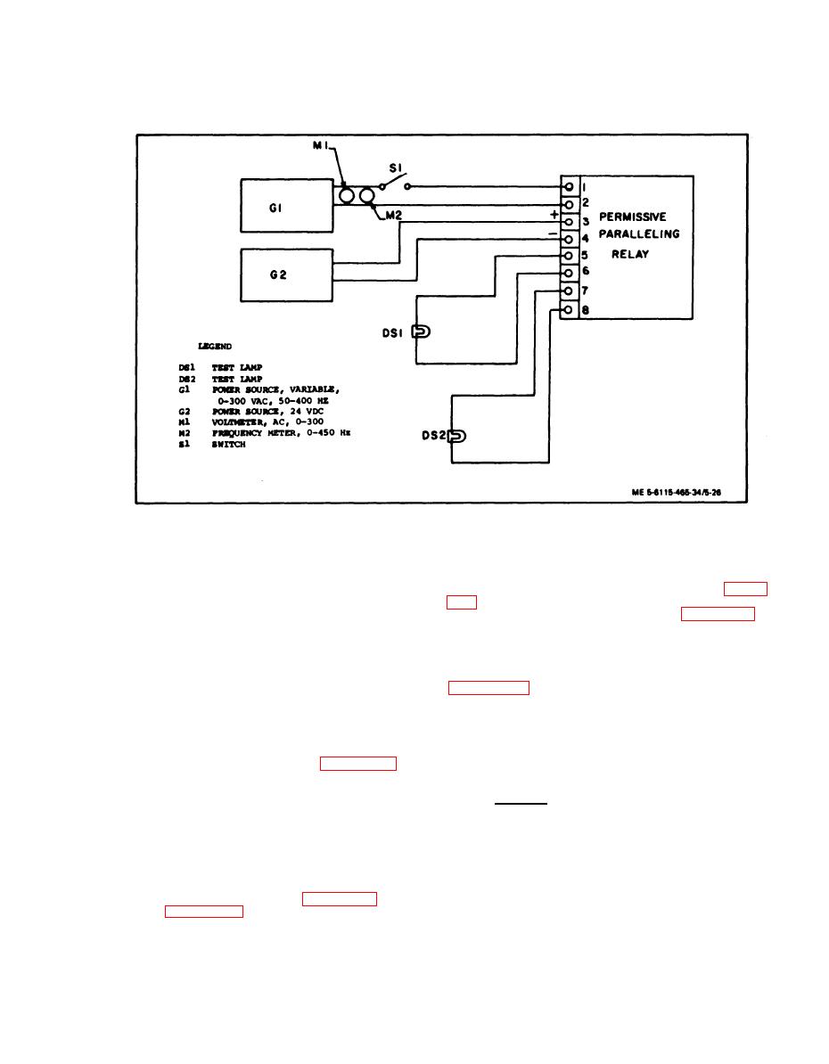
Figure 5-26.
Permissive Paralleling Relay Test Circuit
(14) If the wirinq harness has sustained dam-
(j) Open switch (S1) and adjust the fre-
age and requires repair or rebuild, refer to figure
quency of power source G1 to 400 Hz.
fication and material requirements and Appendix A
(k) Repeat steps (e) through (g) above.
for detailed soldering and replacement procedures.
Relay drop out and pick up shall occur at the same
voltages.
(15) Check individual wires for continuity.
Replace defective wires usinq wire conforming to
(1) Increase the voltage of power source
Military Specification MIL-W-5086, Type II. Use
G1 to 300 Vac for 2 seconds. There shall be no
damage as a result of this test.
d. Assembly. Assemble precise relay assembly
(11) Replace relays which fail to perform as
in reverse order of removal procedures.
specified.
e. Installation. Install precise relay assem-
(12) Test electronic components assembly as
bly in reverse order of removal procedures.
follows: (See schematic diagram in figure 5-27.)
5-13.
STATIC EXCITER AND VOLTAGE REGULATOR
(a) Check resistance across terminals 1
ASSEMBLY.
and 2 and across terminals 3 and 4. Resistance
should be as specified. If it is not, replace the
a. General. The static exciter and voltage
defective resistors as necessary.
regulator assembly provide excitation and voltage
regulation for the generator assembly. The voltage
(b) Test capacitor (terminals 5 and 6).
regulator senses generator output voltage and com-
Replace, if defective.
pares it to a reference voltaqewhich irs established
by the voltage adjust rheostat on the generator set
(13) Replace defective components of elec-
control cubicle. If difference exists, an error
tronic components assembly using figure 5-27 as a
signal is sent to the static exciter. Excitation
guide, and Appendix A references for detailed
current supplied by the current transformer assembly
soldering and replacement procedures.
is altered by the error signal until generator
output voltage equals the reference voltage.
5-37


