TM 5-6115-465-12
TO 35C2-3-466-1
NAVFAC P-8-625-12
TM 06858B/06859D-12
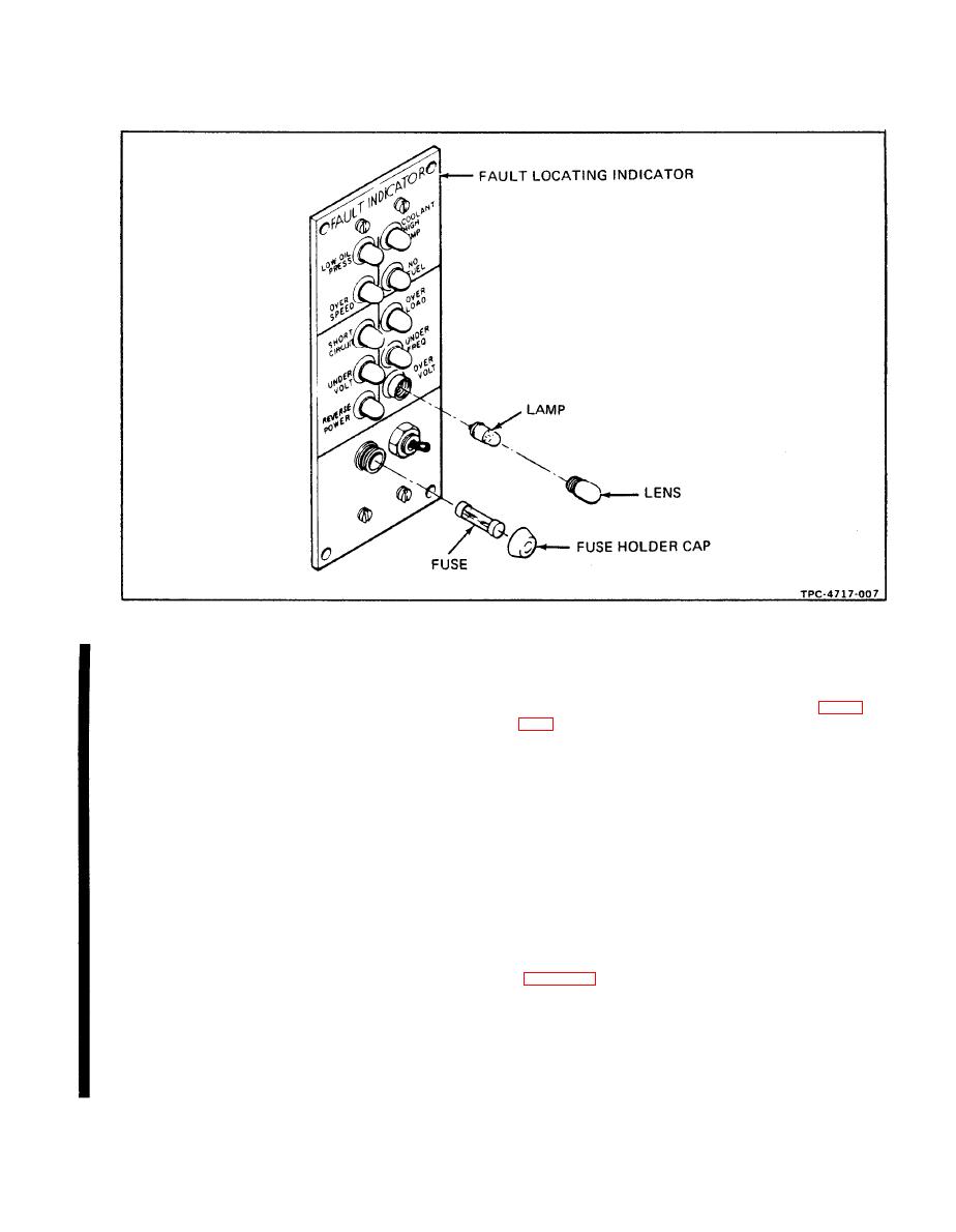
f. Disassembly.
a.
Inspection.
(1) Remove screw and captive washer assemblies
(3) and cover plate (4).
(1) Inspect manual speed control knob (figure
(2) Remove screw and captive washer assemblies
of boot.
(5) and carefully pull indicator panel assembly (6) away
(2) Inspect control cable assembly for corrosion,
from housing. Tag and disconnect electrical leads.
pinched, frayed, or otherwise damaged cable, pinched or
damaged housing, insecure mounting, and stripped or other-
(3) Disassemble panel assembly (items 7 through
wise damaged adjusting threads.
24) only as is necessary for replacement of damaged or
defective components.
b. Testing.
(4) Remove screw and captive washer assemblies
(1) On precise models of the generator set, the
(25) to remove cover plate assembly (26). Tag and discon-
manual speed control must be connected as follows:
nect electrical leads.
(a) Push manual speed control all the way in.
(5) Disassemble cover plate assembly (items 27
(b) Insert manual speed control cable through
through 32) only as is necessary for testing and replacement
sleeve of fuel injection pump manual throttle control arm
of components.
(c) Install and tighten adjustment screw.
(6) Remove screw and captive washer assemblies
(33) to remove wiring harness (34) from housing (35).
(d) Install lockwire.
(2) Check manual speed control for unrestricted
g. Installation. Install fault locating indicator assem-
movement.
bly in reverse order of disassembly and removal procedures.
Change 12


