TM 5-6115-465-12
TO 35C2-3-446-1
NAVFAC P-8-625-12
TM 06858B/06859D-12
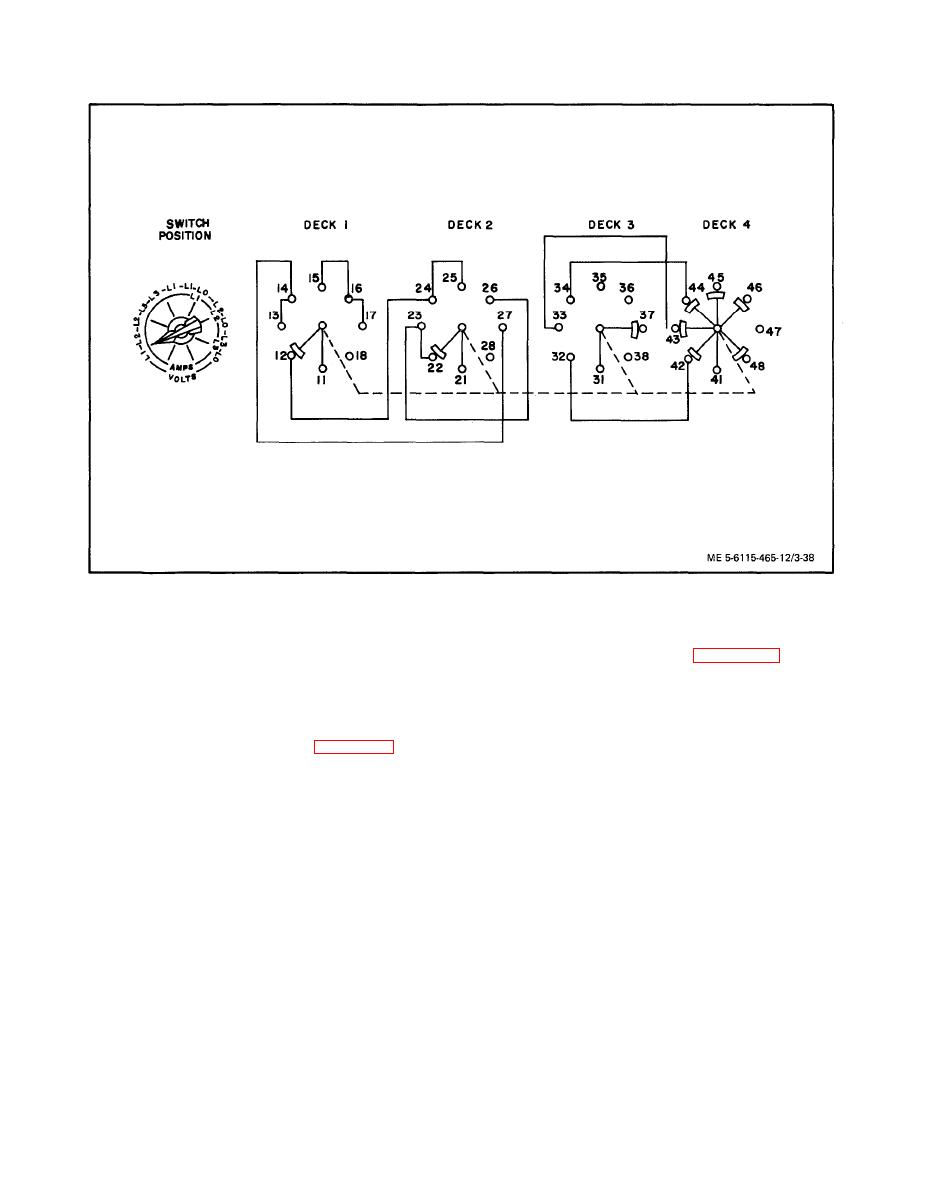
Volts-Amps Transfer Switch Schematic Diagram
(b) Remove nut (41, figure 3-37, sheet 1
(c) Rotate switch shaft clockwise to the
of 3) to remove panel light assemblies (42).
next position and again check switch continuity.
(c) Remove covers (43) and unscrew
lamps (44) from bases (45).
NOTE
(2) Cleaning and Inspection.
The wiper contacts shown in figure 3-38
rotate clockwise to the next set of station-
(a) Clean panel light assemblies with
ary contacts when the switch shaft is ro-
filtered compressed air and a soft bristle brush or
tated clockwise to the next position.
wipe with a clean, lint-free cloth lightly moistened
with an approved solvent.
(d) Continue rotating switch shaft and
checking continuity until all six positions have been
(b) Visually inspect base for corrosion,
checked.
cracks, stripped or otherwise damaged threads, and
evidence of shorting or other damage.
(e) If a discontinuity is noted in any
switch position, switch is unserviceable and shall be
(c) Visually inspect lamp for corrosion,
replaced.
burned out filament, and stripped or otherwise dam-
aged threads.
(4) Installation. Install volts-amps transfer
switch in reverse order of removal procedures.
(d) Visually inspect covers for cracks,
corrosion, stripped or damaged threads and other
m.
Panel Light Assemblies.
damage.
(1) Removal and Disassembly.
(e) Replace any damaged or defective
(a) Tag and disconnect electrical leads to
parts.
panel light assemblies.


