P-8-627-34 T O 35C2-3-442-2
TM-07464A-35 TM 5-6115-457-34
b. Secure relay, relay socket, and
terminal strip in position and secure with
screws, washers, and nuts.
c. After replacement of components on
the printed circuit board, coat the board
with protective coating, conforming to
Military Specification MIL-I-46058, grade
S, type PUR, 0.0050 minimum thickness.
The coating shall be applied so that it
anchors the components to the board.
Terminals utilized for connection to external
circuits shall not be coated.
13-19. INSTALLATION. Refer to figure
13-4 and install the load dumping relay as
follows :
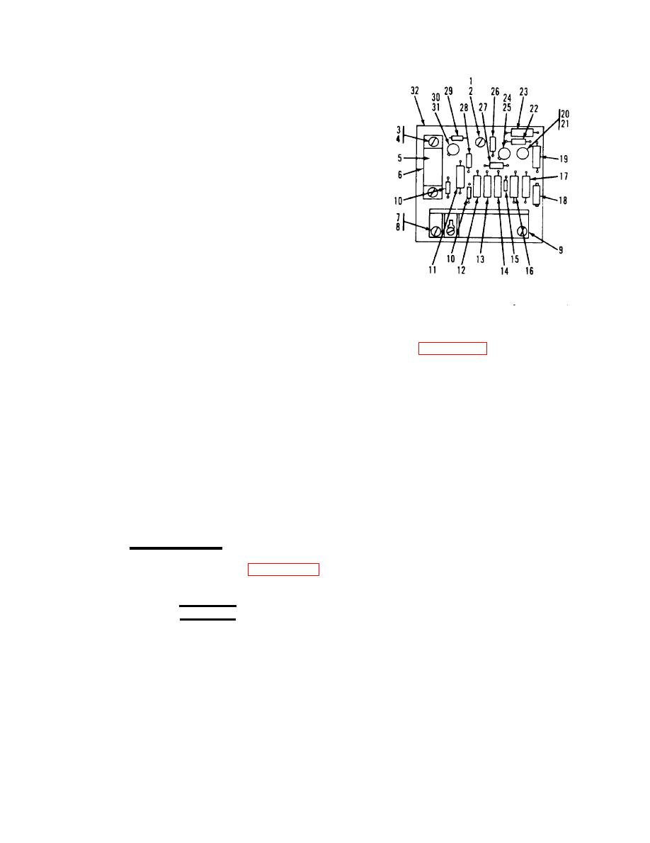
Figure 13-6. Dummy load kits load
a. Connect load dumping relay (45) to
dumping relay (K5).
frame (91) and secure with screws (44).
Legend to figure 13-6.
NOTE
17.
Resistor
1.
Screw
18.
2.
Spacer
Variable resistor
Dummy load kit wiring diagrams
19.
3.
Resistor
Screw (2)
is contained in the Operator and
Lock washer (2)
20.
4.
Transistor
Organizational Maintenance Manual.
21.
Transistor pad
5.
Relay
6.
Resistor
Relay socket
22.
b. Connect electrical wiring to relay.
23.
7.
Resistor
Screw (2)
Check wiring for proper connection.
24.
8.
Transistor
Spacer (2)
9.
Transistor pad
Terminal board
25.
c. Install cover (11) and secure with
26.
Resistor
Diode (2)
10.
screws (9) and washers (10).
27.
Resistor
Resistor
11.
28.
12.
Resistor
Capacitor
13-20. CONTROL BOX.
29.
Resistor
13.
30.
Transistor
Resistor
14.
13-21. REMOVAL, Refer to figure 13-1
31.
15.
Transistor pad
and remove control box as follows:
32.
Board
16.
Zener diode
b. Tag and disconnect frame harness
WARNING
wires from control box components.
Make sure dummy load kit is not
connected to generator set prior to
performing maintenance.
c. Disconnect control box (63) from
a. Disconnect cover (57) by removing
frame (70) by removing screws (58) and
serews (54), and washers (55 and 56).
washers (59 and 60).
Change 8 13-17


