TM 5-6115-400-35
terminal of the output receptacle and the lower contacts
of the cutout relay. See figure 2.
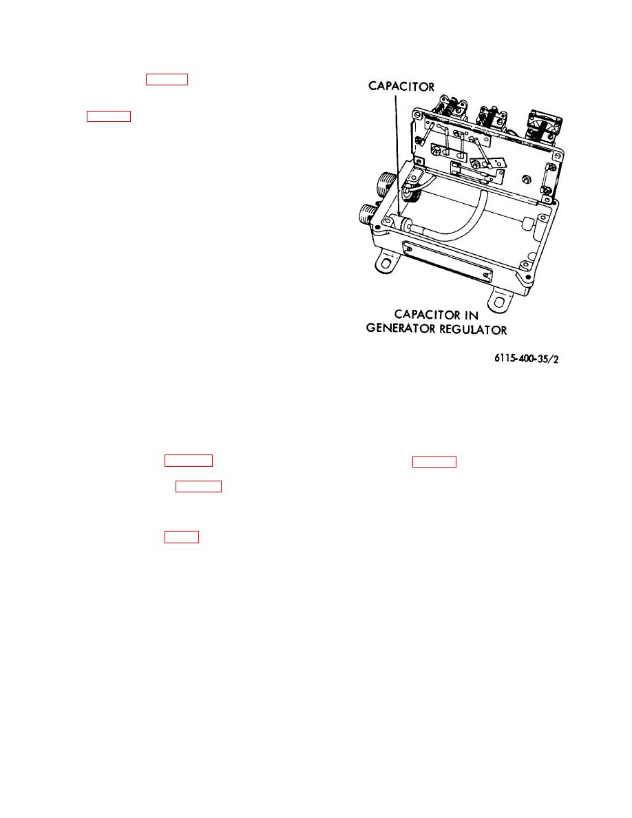
26. Replacement of Suppression Components
Refer to figure 2 and replace the radio interference
suppression components.
Figure 2. Radio Interference suppression
components.
Section IV. REMOVAL AND INSTALLATION OF MAJOR COMPONENTS
27. Housing
(1) See figure 3 and remove housing top and
housing.
rear side covers, louver doors, and
louvers.
housing.
(2) Remove paralleling receptacles (located
near control panel).
28. Engine
a. General The engine is supported in front by the
(3) Remove relay box to control panel wiring
front mounting bracket (fig. 4) secured to a cross
harness.
member of the generator set base. The engine is
(4) Remove 120 VAC outlet plugs (located
supported in the rear by the main generator which is
near control panel).
bolted to supporting plates welded into the generator set
(5) Cut wire connections to fuse holder
base.
(located between 120 VAC outlet plugs
b. Removal.
and paralleling receptacles). These wires
Note
must be reconnected and soldered for
To remove the engine, it is necessary
reassembly.
to remove the engine and generator
(6) Disconnect all wiring harnesses from the
as an assembly and separate the
control panel.
engine from the generator after
(7) Disconnect harnesses from the electric
removal. However, the generator can
governor control unit.
be removed with the engine in the
set.
16


