TM 9-6115-660-13&P
INSTALLATION
1.
2.
3.
4.
5.
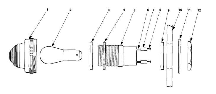
Insert terminaI leads (7) through opening in switch box housing (10) and pull
rests against switch box cover (10).
Install lock washer (11) and mounting nut (12).
Connect terminal lugs (8) to switch box components in accordance with table 4-2.
Insert lamp (2) and O-ring (3) into lens (1).
Install lens (1) into housing (4) and hand tighten.
through until O-ring (9)
4-15 SYNCHRONIZING LIGHT MAINTENANCE.
This task covers: a. Test
c. Installation
b. Removal
INITIAL SETUP
Tools
Equipment Conditions
Tool Kit, General Mechanic’s
Reference
(item 1, appendix B)
Both generator sets shut down;
Materials/Parts
paragraph 2-5.3.3.
Switch box cover open.
Solder
Figure 4-15. Synchronizing Light
4-30