TM 9-6115-659-13&P
REPAIR
Refer to figure G-4, appendix G.
INSTALLATION
1. Install output connector(4), chain (3) atttached to dust cover, four screws (1), eight flat washers (2),
four lock washers (6), and nuts (7).
2. Refer to wiring diagram (figure FO-1) and tags placed on leads during removal, and install leads (10),
internal tooth washers (9), and nuts (8) on load terminals (11).
5-11 RELAYS K3-K6 MAINTENANCE.
This task covers: a. Removal
c. Installation
b. Test
INITIAL SETUP
Tools
Equipment Conditions
Tool Kit, General Mechanic’s
Reference
(item 1, appendix B)
Multimeter (item 3, appendix B)
Both generator sets shut down; paragraph
24 VDC Power Source (item 3, appendix B)
2-5.3.3. Trailer handbrakes set, front support
leg/landing lowered, and rear leveling-support
Materials/Parts
jack lowered; paragraph 2-3.2.1. Switch box
cover open.
Lock washers
REMOVAL
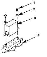
Remove two screws (1, figure 5-16), washers (2), and relays (3) horn relay sockets (4).
Figure 5-16. Relay K3-K6 Removal.
5-29

