Google+
Facebook
LinkedIn
Twitter
Digg
StumbleUpon
Home
Download PDF
Order CD-ROM
Order in Print
Figure 5-11. Disconnect Switch Box Harness W9 From Contactor.
INSTALLATION - TM-9-6115-659-13P_183
TM-9-6115-659-13P Power Unit PU-732/M (NSN 6115-00-280-3082) MEP-118A 15 Kw 400 Hz Generator Set M200A1 2-Wheel 4-Tire Modified Trailer Manual
Page Navigation
150
151
152
153
154
155
156
157
158
159
160
TM 9-6115-659-13&P
3. Remove insulation from W9-20 and W9-49 connections to resistor R3 and un
solder
harness leads.
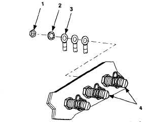
4. Remove nut (1, figure 5-12), internal tooth washer (2), and W9 harness lead (3) from load terminals
L0 and L3 (4).
Figure 5-12. Switch Box Load Terminals.
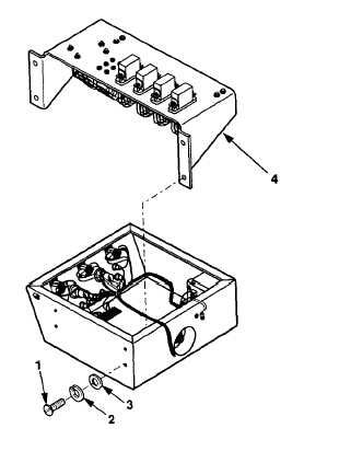
5. Remove four screws (1, figure 5-13), lock washers (2), and flat washers (3), and invert
relay
board
assembly (4).
Figure 5-13.
Relay
Board Assembly Removal.
5-22
Integrated Publishing, Inc. - A (SDVOSB) Service Disabled Veteran Owned Small Business