TM 9-6115-604-34
NAVFAC P-8-633-34
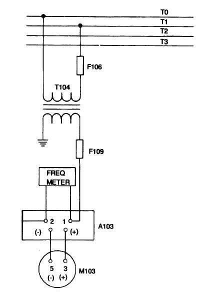
Figure 10-11. Frequency Transducer A103, On Equipment Test Setup
(7)
If the conditions of steps (3) and (5), above, have been met, then the power factor transducer PFr is good
and the test is over. If conditions have not been met, further testing is required to determine if transducer
PFT is defective or it some other related circuit elements are responsible for the unsatisfactory readings.
Proceed with step (8), below.
(8)
Open upper cabinet B door. Refer to Figure 10-12. Install an ammeter in the line connected to power
factor transducer PFT terminal 6. Connect an AC voltmeter across PFT terminals 8 and 12. Connect a
microammeter in the line connected to PFT terminal 2.
(9)
Perform steps (1) and (2), above.
(10)
Verify the following: (a) The voltmeter reads 110 to 130 V ac.
(a)
The ammeter reads 2.95 to 3.00 amperes.
(b)
The microammeter reads zero.
(11)
Without decreasing load bank resistance, increase load bank reactance until the ammeter indicates 3.68 to
3.74 amperes.
10-22