TM 9-6115-604-34
NAVFAC P-8-633-34
(13)
Install the lockwashers (8), capscrews (6 and 7), and snugtighten the capscrews to approximately 25
pound-inches (3 newton-meters).
(14)
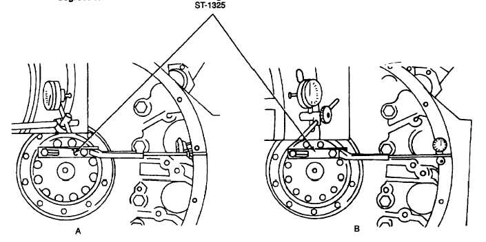
Check the flywheel housing (9, Figure 9-62) alignment and tighten the capscrews (6 and 7) as follows:
(a)
See Figure 9-65. Attach dial gage attachment, ST-1 325, and dial indicator to the crankshaft, and
position the indicator button on the housing bore (A, Figure 9-64).
(b)
Draw chalk marks on the flywheel housing at 12, 3, 6, and 9 O'clock
(c)
Check the readings at 3 and 9 O'clock. I the TIR exceeds 0.010 inch (0.25 mm), use a soft hammer to
tap the housing right or left, as necessary, one-half the distance of the TIR to center the housing
horizontally.
(d)
Check the readings at 12 and 6 o'clock. If the TIR exceeds 0.010 inch (0.25 mm), use a soft hammer
to tap the housing up or down, as necessary, one-half of the TIR to center the housing vertically.
(e)
Move the dial indicator to the face of the flywheel housing (B, Figure 9-65).
(f)
Push the crankshaft forward to take up the end clearance. Zero the indicator, and rotate the crankshaft
360 decrees to obtain the TIR of the housing face.
Figure 9-65. Checking Flywheel Housing Alignment
(g)
The TIR of the housing face must not exceed 0.010 inch (0.25 mm).
(h)
To correct the housing face runout, remove the housing, check the dust seal alignment and remove
any burrs or dirt from the mating surfaces. Reinstall and realign the housing. If the alignment is still
incorrect. replace the housing.
(i)
If the indicator readings are within the limits, cross tighten the capscrews (6 and 7, Figure 9-62) in
three steps to 260 to 270 pound-feet (353 to 363 newton-meters).
(15)
Install the starter motors in accordance with the Operator and Organizational Maintenance Manual.
(16)
Install the flywheel in accordance with paragraph 9-34.
9-36. FRONT ENGINE SUPPORT MAINTENANCE.
a.
Remove.
(1)
Remove the cooling fan shrouds in accordance with the Operator and Organizational Maintenance Manual.
(2)
Remove the hexagon head capscrews (1, Figure 9-66), hexagonal nuts (2), lockwashers (3), and bevel
washers (5) securing the front support assembly (6) to the front engine support (5). I damaged, remove the
grease fitting (9)
9-115