TM 9-6115-604-34
NAVFAC P-8-633-34
e.
Install.
(1)
Bolt a sling to the flywheel (3, Figure 9-62) at the 10 and 2 O'clock positions and attach to an overhead
hoist.
NOTE
Before installing the flywheel, be sure the mating surfaces of the flywheel and crankshaft are
dean, and free of burrs.
(2)
Install the roll pins (4) if removed.
(3)
Position the flywheel and crankshaft as necessary so that the capscrew holes and roll pin holes are in
alignment, and install the flywheel over the guide studs.
(4)
Lubricate the threads of the capscrews and washers (1) with lubricating oil, MIL-L-2104, and lubricate the
washers (2) with SAE 140 gear lubricant, MIL-L-2105.
(5)
Install ten washers (2), and capscrews and washers (1) and tighten them hand tight. Remove the guide
studs, and install the remaining two capscrews and washers hand tight.
(6)
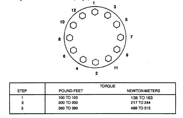
Tighten all capscrews and washers (1) using the sequence, steps, and torque shown in Figure 9-63.
(7)
Attach a dial indicator to the flywheel housing using attachment ST-1 325 and check the pilot bore runout
(A, Figure 9-64). The TIR shall not exceed 0.005 inch (0.13 mm).
NOTE
When checking the flywheel face runout, be sure the crankshaft is kept positioned all the way
forward to remove all crankshaft end-play.
(8)
Move the dial indicator to the flywheel face to indicate a radius of 10 inches (254 mm), and check the face
runout (B, Figure 9-64). The TIR shall not exceed 0.010 inch (0.25 mm).
(9)
If the pilot bore or face runout is excessive, remove the flywheel and check for dirt or burrs on the mating
surface of the flywheel or crankshaft. If the runout is still excessive after removing any dirt or burrs,
replace the flywheel.
(10)
Install the generator in accordance with paragraph 2-16.
Figure 9-63. Flywheel Capscrew Tightening Procedure
9-112


