TM 9-6115-604-34
NAVFAC P-8-633-34
(3)
Using a dial indicator, check the centers on the head stock and tail stock of the crankshaft grinding machine
for runout. Both head stock and tail stock must be on center within 0.001 inch (0.03 mm) TIR.
(4)
Adjust the tail stock of the grinding machine to accommodate the length of the crankshaft.
(5)
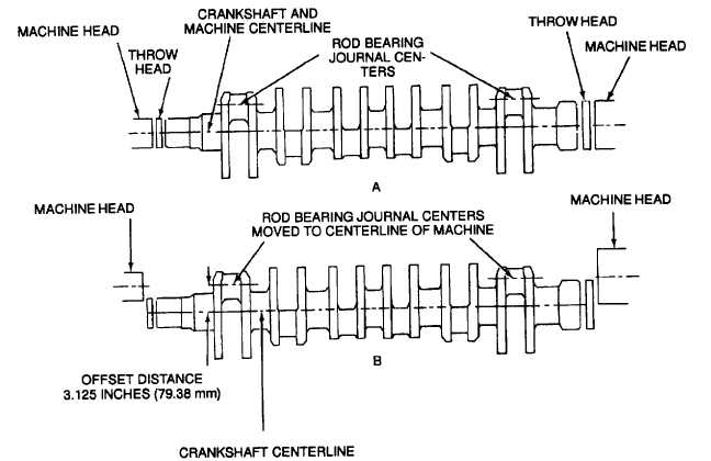
Adjust the crankshaft grinding machine to grind the rod bearing journals by offsetting both the head stock and
the tail stock 3.125 inch (79.38 mm). Offsetting the head stock and tail stock allows the rod bearing journals
of the crankshaft to turn about the centerline of the grinding machine (B, Figure 9-50).
(6)
Because the crankshaft will be offset in the machine while grinding the rod bearing journals, it will be
necessary to counterbalance the crankshaft with an equal amount of weight. Adjust the counterweights on
the crankshaft grinding machine to counterbalance the crankshaft.
(7)
Adjust the indicator on the Arnold gage to the proper journal dimension to monitor the amount of material
being removed from the journal.
(8)
Mount the crankshaft in the grinding machine. Locate and lock both throw heads at 0 index. Position the
crankshaft in the machine with the No.1 throw (or whichever throw is to be ground first) at top center. Use a
horizontal vee gage to ensure accuracy, and damp the crankshaft in position. When the throw heads of the
machine are released, the crankshaft should center on the rod bearing journals.
(9)
Set up the rod bearing journal to be ground using a dial indicator. To obtain an accurate reading, the
crankshaft must be rotating in the machine at the speed at which it will be ground. This is important because
the weight of the crankshaft is off center, and the crankshaft will tend to bow during rotation. When the
grinding machine throw heads are moved to make an adjustment, both heads must be moved the same
amount. This will maintain parallelism and taper within specifications. The rod bearing journals shall be on
center to within 0.001 inch (0.03 mm) TIR.
Figure 9-50. Crankshaft Offset To Grind Connecting Rod Bearing Journals
9-87

