TM 9-6115-604-34
NAVFAC P-8-633-34
NOTE
The backlash indicator reading on the water pump drive gear may not be accurate without the
support gear cover and pulley installation. A slight movement between the gears should be
felt as the pulley is moved first clockwise then counterclockwise after the installation is
complete.
NOTE
Injection timing must be checked whenever a new camshaft or gear is installed. Timing
adjustments are made by changing the camshaft keys. Timing the No. 1 cylinder on each
bank will accomplish injector timing for all cylinders.
(19)
Check and adjust the injector timing as follows:
(a)
Remove the fuel injector from No. 1 cylinders in accordance with the Operator and Organizational
Maintenance Manual.
(b)
Remove the rocker arms from No. 1 cylinders in accordance with paragraph 9-5.
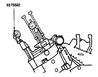
Figure 9-21. Injector Timing Setup
(c)
Position the timing fixture 3375522 in the injector well of the cylinder being checked, engaging the
push rod indicator in the injector push rod (Figure 9-21). Tighten the hold-downs evenly by hand.
(d)
Loosen both of the indicator supports. Rotate the crankshaft in the direction of the engine rotation to
TC (top center) on the compression stroke. At TC, the piston travel indicator plunger will be near the
full upward position. Adjust both of the indicators to their fully compressed position, and, to prevent
damage to the indicators, raise both indicators approximately 0.020 inch (0.05 mm). Lock-them in
place with the setscrew.
(e)
Rotate the crankshaft back and forth to assure the piston is precisely at TC on the compression
stroke (1, Figure 9-22). TC is indicated by the maximum clockwise position of the piston travel
indicator pointer. Turn the piston travel indicator face to align the zero with the pointer. Lock the
face with the thumbscrew.
NOTE
Both indicators will move in the same direction when the piston is on the compression stroke.
I the push tube indicator does not move in the same direction as the piston indicator, rotate
the crankshaft one complete revolution to place the piston on the compression stroke and
repeat step (g), above.
(f)
Rotate the crankshaft in the direction of the engine rotation (2, Figure 9-22) approximately 90
degrees ATC (after top center). Turn the push rod travel indicator face to align the zero with the
pointer. Lock the face with the thumbscrew.
9-41


