TM 9-6115-604-34
NAVFAC P-8-633-34
(e)
Install the gear, shaft, and bearing assembly into the block indexing the timing marks (2 and 6,
Figure 9-16).
(f)
Lubricate the threads of the center bolt (33, Figure 9-15) with dean engine lubricating oil, install the
center bolt and washer (33 and 34) and tighten to 175 to 185 pound-feet (237 to 251 newton-meters).
(15)
Check to be sure that all timing marks are aligned in accordance with Figure 9-16.
(16)
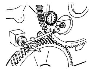
Attach a dial indicator (Figure 9-19) to the housing and check the camshaft end clearance. The end
clearance shall be 0.006 to 0.013 inch (0.15 to 0.33 mm) on both camshafts. If the end clearance is not
within the limits, remove the camshaft gear and change the thrust plate (32, Figure 9-15).
(17)
Repeat step NO TAG, above, to measure the end clearance fort he other gears. The end clearances must
be within the tolerance given in Figure 9-16.
Figure 9-19. Measuring Camshaft End Clearance
(18)
Check the gear train backlash as follows:
(a)
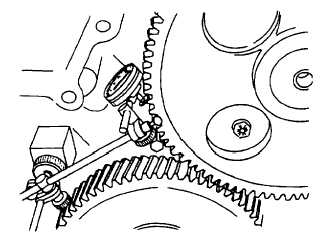
Attach a dial indicator to the gear housing with the plunger on a tooth of the gear to be checked
(Figure 9-20).
(b)
Lock the mating gears in position, rotate the gear being checked to take up the backlash, and zero
the indicator.
(c)
Rotate the gear in the opposite direction, and read the gear backlash on the indicator gage. The
backlash should be 0.003 to 0.015 inch (0.076 to 0.38 mm) on all gears.
(d)
Move the dial indicator to the next gear and repeat the above procedure for each gear.
Figure 9-20. Measuring Timing Gear Backlash
9-40


