TM 9-6115-604-34
NAVFAC P-8-633-34
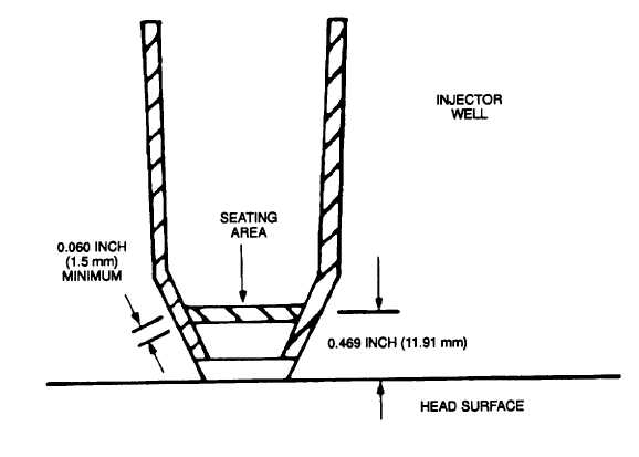
Figure 9-7. Injector Seat Pattern
NEW
REF
MIN
MAX
WEAR
LIMIT
INCH
INCH
(mm)
(mm)
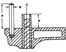
A
2.350
2.370
(59.69)
(60.20)
B
0.433
0.4335
0.432
(11.00)
(11.011)
(10.97)
C
0.4972
0.4980
0.4996
(12.629)
(12.649)
(12.690)
D
13.75
13.90
(34.93)
(35.31)
Figure 9-8. Inspection of Valve Crosshead Guides and Valve Guides
9-13