TM 9-6111-604-34
NAVFAC P-8-633-34
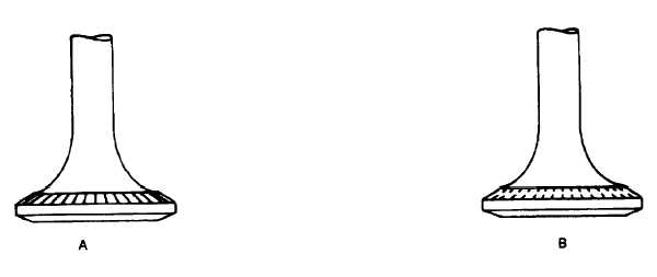
Figure 9-10. Testing of Valve Seating
d.
Seating Check. Check each valve for proper seating as follows:
(1)
Using a common lead pencil, mark radial lines on the valve face (A, Figure 9-10).
(2)
Position the valve in the guide against the seat insert.
(3)
Using moderate hand pressure, hold the valve against the seat, rotate it 10 degrees, and remove the
valve from the head.
(4)
Visually examine the pencilled lines; a good surface is indicated if all pencilled lines are broken at the
approximate center of the valve face (B, Figure 9-10).
(5)
If all pencilled lines are not broken, check the valve grinding equipment for proper adjustment,
operation, and stone dressing.
(6)
If the pencilled lines are broken at the inner diameter of the valve face, the seat must be narrowed at
area D (Figure 9-9) using a stone dressed to an included angle of 60 degrees. f the pencilled lines are
broken at the outer diameter of the face, narrow the seat at area C using a stone dressed to an angle
of 15 degrees.
(7)
When properly narrowed, the seat width will be 0.060 to 0.100 inch (1.52 to 2.54 mm), and the
pencilled lines will be broken at the approximate center of the valve face.
(8)
Narrowing may be done at both area C and D if necessary. When narrowing at area C, however, take
care that grinding does not extend into the head metal and remove the seat insert staking. Removal of
the staking metal will result in a loose valve seat insert.
NOTE
Valve sealing surfaces that are properly ground and narrowed on
precision equipment should not need lapping to obtain a good
seal. If necessary to pass the vacuum test, however, a small
amount of lapping is permissible.
e.
Valve Installation. Install the intake and exhaust valves as follows (see Figure 9-1).
(1)
Dip the valve stem in dean preservative of MIL-L-21260, and install the exhaust or intake valve (5 or
6) through the guide being careful to keep oil from the valve seat and face.
(2)
Install the valve spring guide (4), valve spring seat (2), and new locks (1). Do not install the spring (3)
at this time.
(3)
Pull up on the spring seat (2) and, while pulling on the seat, measure the distance between the spring
seat surface of the seat (2) and the valve spring guide (4). This is the valve spring assembled height
and should not measure over 2.470 inches (62.74 mm) (see Table 1-4).
9-16