TM 9-6115-604-34
NAVFAC P-8-633-34
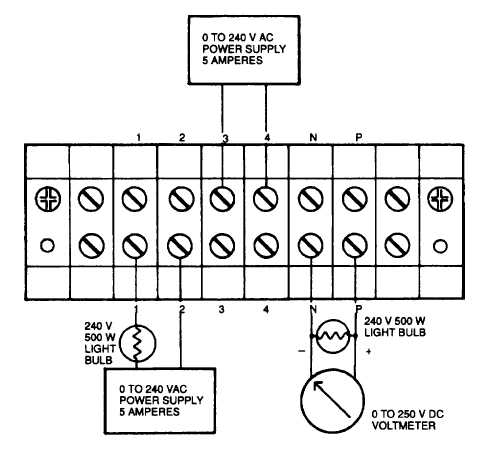
Figure 5-40. Test Setup, Current Boost Module A101
(4)
Turn on power supply to terminals 1 and 2 and adjust voltage up and down observing the DC voltage on
terminals N and P increases and decreases but does not go above 180 volts. Now adjust power supply 60
the DC voltmeter reads 100 volts.
(5)
Now adjust power supply to terminals 3 and 4 above 240 VAC and the DC voltmeter should read about
zero. The power supply on terminals 1 and 2 should indicate some amperage which is dependent on its
load resistor. Now adjust this power supply voltage below 240 VAC the DC voltmeter should read 100
volts as set in above step. Replace current boost module if it fails the above test.
(6)
Turn off both power supplies and disconnect all wiring used in the above steps.
(7)
Reconnect wiring to the current boost module A101 and discard tags.
(8)
Shut upper cabinet B door and set MAINTENANCE LOCKOUT switch S100 to OPERATE.
5-94