TM 9-6115-604-34
NAVFAC P-8-633-34
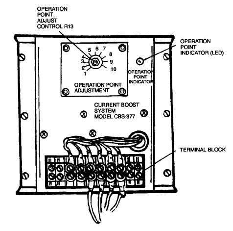
Figure 5-39. Current Boost Module A101, Adjusting
d.
Remove.
(1)
Set MAINTENANCE LOCKOUT switch S100 to MAINTENANCE.
(2)
Open door to upper cabinet B.
(3)
Tag and disconnect wires from current boost module A101 (33, Figure 5-9).
(4)
Remove six screws and captive washer assemblies (34) and remove current boost module A101 (33).
e.
Test. See Figure 5-39 and Figure 5-40.
CAUTION
High potential test equipment must not be used. Use of such equipment may destroy the
semiconductors In current boost module A 101.
(1)
Connect a 0 to 300 volt AC variable power supply with voltmeter, and ampermeter that has a five amp
capacity across terminals 1 and 2, and a load resistor in series such as 500 watt 240 volt light bulb. Also
connect another like power supply to terminals 3 and 4 of current boost module A101.
(2)
Connect a DC voltmeter and load (such as a 240 volt 500 watt light bulb) to terminals N and P of current
boost module A101.
(3)
Turn on power supply to terminals 3 and 4 then adjust voltage to 240 VAC. Rotate operation point adjust
control R13 to just turn out operation point indicator (LED). Lower power supply voltage to 200 VAC
operation point indicator should light.
5-93