ARMY TM 9-6115-604-12
NAVY NAVFC P-8-633-12
NOTE
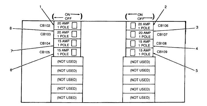
CIRCUIT BREAKERS ARE SHOWN SET TO THEIR NORMAL OPERATING POSITIONS.
Figure 2-8. Distribution Panel DP1 Controls
Table 2-8. Distribution Panel DP1, Controls and Indicators
Figure 2-8, 1
Control room receptacles circuit To provide power and circuit protection
ON
breaker CB102
to control room receptacles J102 and
J103
Figure 2-8, 2
Engine room receptacles circuit
To provide power and circuit protection
ON
breaker CB106
to engine room receptacles J106 and
J107
Figure 2-8, 3
Engine room receptacles circuit
To provide power and circuit protection
ON
breaker CB107
to engine room receptacles J108 and
J109.
Figure 2-8, 4
Engine room lighting circuit
To provide power and circuit protection
ON
breaker CB108
to engine room lights DS103 and
DS104.
Figure 2-8, 5
Control room circuit breaker
To provide power and circuit protection
ON or OFF, as
CB109
to control room fan motor B103.
comfort dictates
FIGURE
AND
INDEX NO.
CONTROL OR
INSTRUMENT
FUNCTION
NORMAL
READING/
SETTING AT
RATED LOAD
2-19


