ARMY TM 9-6115-604-12
NAVY NAVFAC P 8 633-12
4-107. GEN/BUS VOLTMETER SWITCH S112 (24, Figure 2-2). GEN/BUS VOLTMETER switch S112 is a two-section,
rotary tap-switch contact design An integral detent assembly provides positive click stops at all eight positions. The
switch is used in conjunction with AC KILOVOLTS meter M101 to select any one of the three generator phases at either
the generator G1 or at the bus to check for voltage levels.
NOTE
Switch wirng position numbers are translated as follows. the first digit defines the
section, or deck, in relation to the handle end; the second digit Is a specific terminal on
that deck. For example, position 23 is located on the second deck, the contact is
terminal number 3.
a.
Test.
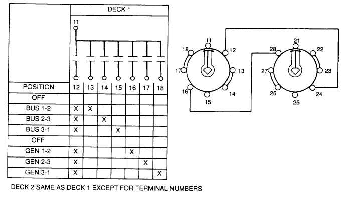
(1) Tag and disconnect wiring to switch contacts See Figure 4-70.
(2) Set a multimeter to RX1 scale and test for contact continuity in the switch positions specified in chart in
Figure 4-70. Meter should indicate zero ohms at all points marked in the chart.
(3) Multimeter should indicate Infinity at all blank contacts in the chart.
b.
Remove. See Figure 4-66.
(1) Remove screw in center of handle and slide handle off shaft.
(2) Remove three screws from face of mounting plate on front of door (10) Switch sections can be removed at
rear of cabinet B door as an assembly.
Figure 4-70. Test Data for GEN/BUS VOLTMETER Switch S112
4-173


