ARMY TM 9-6115-604-12
NAVY NAVFAC P 8 633-12
4-105. BREAKER CONTROL SWITCH S4 (20, Figure 2-2). BREAKER CONTROL switch S4 is a three-section (or
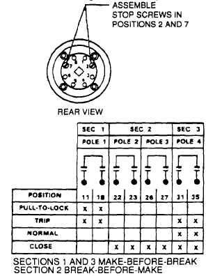
deck) rotary, dual contact design. The chart In Figure 4-67 specifies contact continuity in both positions, TRIP and
CLOSE. BREAKER CONTROL switch S4 is used to energize close and trip coils of load circuit breaker C8101.
Figure 4-67. Test Data For BREAKER CONTROL Switch S4
a.
Test.
(1) Tag and disconnect wiring to BREAKER CONTROL switch S4.
NOTE
Switch wirng position numbers are translated as follows: the first digit defines the
section, or deck, in relation to the handle end, the second digit is a specific terminal on
that deck. For example position 23 is located on the second deck, the contact is
terminal number three.
(2) Set a multimeter to RX1 scale and, test for contact continuity in the switch positions specified. Meter should
indicate zero OHMS at the points marked in chart in Figure 4-67.
(3) Multimeter should indicate Infinity at all open contacts In chart in Figure 4-67.
NOTE
An integral spring return mechanism returns the handle to the normal-vertical position
except in the pull-to-lock position Slip contacts are Incorporated to maintain contact
closure in the last commanded position. These slip contacts are also used for the green
and red breaker Indicator lights DS33 (OPEN) and DS34 (CLOSED).
(4) The target window opening on the face of the switch plate should show green when last command operation
was TRIP.
(5) Target window should show red when last command operation was CLOSE.
(6) Switch handle should always return to normal-vertical position following either command operation, TRIP or
CLOSE.
(7) Failure to meet any of the above requirements necessitates replacement of BREAKER CONTROL switch S4
(20, Figure 2-2).
4-169


