ARMY TM 9-6115-604-12
NAVY NAVFAC P 8 633-12
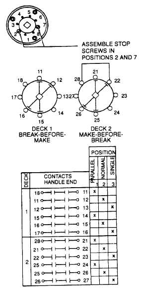
Figure 4-71. Test Data for PARALLEL Switch S6
b
Remove. See Figure 4-68.
(1) Remove screw in center of handle (4) and slide handle off shaft.
(2) Remove four screws from face of mounting plate on door PARALLEL Switch S6 (4) sections can be removed
at rear of cabinet B door as an assembly.
c.
Install. See Figure 4-68.
(1) Install PARALLEL Switch S6 (4) by positioning switch sections at rear of cabinet B door and assemble the
mounting plate from the front Secure the entire assembly with the four mounting screws.
(2) Replace switch handle In the NORMAL position ensuring that shaft Is in the NORMAL condition. Secure
handle with attaching screw.
(3) Connect wires and discard tags.
4-175

