ARMY TM 9-6115-604-12
NAVY NAVFAC P 8 633-12
c.
Repair. Repair consists of replacing defective lamps (13, Figure 4-66) and lamp holders (12). Refer to steps b
and d.
d.
Install. See Figure 4-66.
(1) Install lamp holder (12) In panel. Secure with attaching hardware.
(2) Connect and solder wiring. Cover soldered connection with shrink tubing as needed on lamp holder (7).
(3) Install lamp (13).
(4) Install lens to secure lamp (13).
4116.
SYNCHROSCOPE SWITCH S115 (14, Figure 4-66). SYNCHROSCOPE switch S115 is a two-position switch
with three decks. This switch actuates the synchronizing lights and SYNCHROSCOPE meter M106 and must be set to
ON when attempting to parallel.
a.
Test.
NOTE
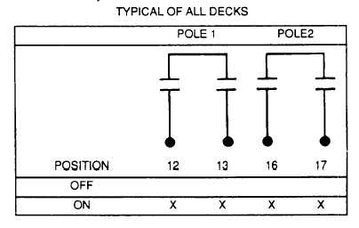
Switch wiring position numbers are translated as follows. the first digit defines the
section or deck, in relation to the handle end; the second digit is a specific terminal on
that deck. For example. position 23 is located on the second deck, the contact is
terminal number 3.
(1) Tag and disconnect wiring to switch contacts See Figure 4-73
(2) Set a multimeter to RX1 scale and test for contact continuity in the switch positions specified in the chart In
Figure 4-73. Meter should indicate zero ohms at all points marked in the chart.
(3) Multimeter should indicate infinity at all blank contacts in the chart.
b.
Remove. See Figure 4-66.
(1) Tag and disconnect wiring to switch (14) contacts.
(2) Remove screw In center of handle and slide handle off shaft.
(3) Remove three screws from face of mounting plate on front of door. Switch (4) sections can be removed at
rear of cabinet B door as an assembly.
Figure 4-73. Test Data for SYNCHROSCOPE Switch S115
4-180