ARMY TM 9-6115-464-12
AIR FORCE TO 35C2-3-445-1
NAVY NAVFAC P-8-624-12
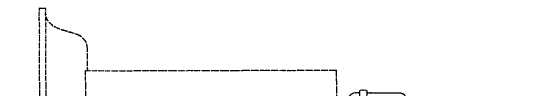
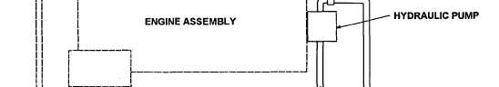
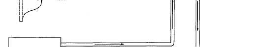
1-20 HYDRAULIC SYSTEM. The hydraulic system (Figure 1–12) is used on the electro-hydraulic governor
equipped precise generator sets. Its function is to provide precise frequency control, The system consists of a sump,
a replaceable element type filter, a gear driven positive displacement type pump, a pressure relief valve, a hydraulic
actuator and interconnecting lines. The hydraulic fluid is pumped from the sump through the hydraulic pump to the
filter. The pressurized filtered fluid is routed through the hydraulic actuator and back to the sump. The actuator hy-
draulically operates the governor control linkage to change the governor setting. Changing the governor setting
increases or decreases the engine speed causing a corresponding increase or decrease in generator output fre-
quency.
Figure 1-12. Hydraulic System Diagram
(Electo-Hydraulic Governor Equipped Precise Sets Only
1-21 ELECTRONIC GOVERNING SYSTEM. The electronic governing system senses speed and load electrical-
ly and provides the controls and load responses for effective single unit or parallel operation. The system consists
of a rheostat for frequency adjustment, a load measuring unit for sensing load changes and a governor control unit
which signals the actuator for rapid governor response.
1-22