ARMY TM 9-6115-464-12
AIR FORCE TO 35C2-3-445-1
NAVY NAVFAC P-8-624-12
1-18 AIR INTAKE AND EXHAUST SYSTEM.
a.
b.
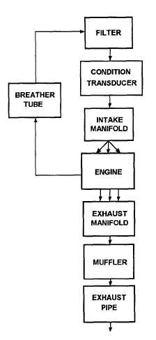
The air intake and exhaust system (Figure 1–10) consists of a filter, restriction indicator, intake manifold,
breather tube, exhaust manifold, muffler, and piping. Ambient air is drawn into an air filter where it passes
through the filter element. Airborne dirt is removed and trapped in the filter. The air cleaner assembly is
equipped with a condition transducer. The condition transducer measures the vacuum created by the air
cleaner condition indicator or when the filter needs servicing. Filtered air is drawn out of the filter through
air intake tubes to the air intake manifold where it passes into the combustion chambers and is mixed with
fuel from the injectors.
The engine exhaust gases are expelled into the exhaust manifold. The exhaust manifold channels the
gases into the muffler that deadens the sound of the exhaust gases. The gases pass from the muffler
through the exhaust piping and are vented upward from the generator set housing. The breather tube
provides an escape route for gases which accumulate in the crankcase during engine operation. The
gases pass through the breather, located in the engine valve cover, and are expelled into the air cleaner
housing through the breather tube.
Figure 1-10. Air Intake and Exhaust System
1-20