ARMY TM 9-6115-464-12
AIR FORCE TO 35C2-3-445-1
NAVY NAVFAC P-8-624-12
1–15 FUEL SYSTEM.
a.
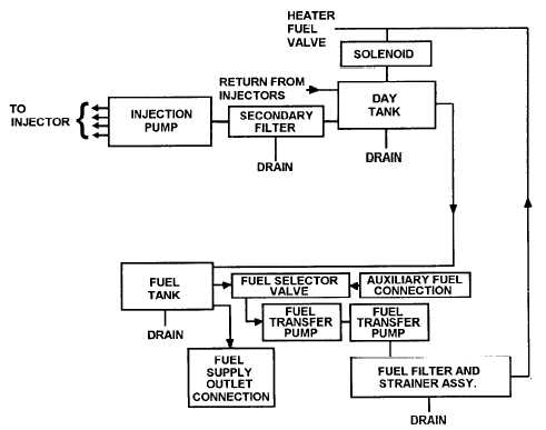
The fuel system (Figure 1–7) consists of piping, fuel tank, transfer pumps, fuel filters, strainer assembly,
heater fuel valve, fuel solenoid, day tank, secondary filters, injection pump, and injectors. Fuel is drawn
from the generator day tank by the transfer pump when the START/RUN/STOP switch is in the RUN posi-
tion. After reaching the transfer pump, fuel passes through a fuel filter and strainer where water is re-
moved. Then the fuel goes through a filter where small impurities are removed. Then the fuel goes through
the fuel solenoid into the day tank and passes through the secondary fuel filter to remove impurities. The
fuel also goes to an injection pump where it is pressurized and forced through the injectors into the com-
bustion chamber, where it is mixed with air and ignited. The unused fuel is returned to the generator day
tank via an excess fuel return line.
b.
The Auxiliary Fuel System consists of a main fuel tank piping and fuel selector valve. When the START/
RUN/STOP switch is set to RUN, it actuates the fuel transfer pumps and transfers fuel from the auxiliary
tank to the generator fuel system. The fuel level gauge is a liquid quantity indicator gauge which is cali-
brated 1/4 increments of tank quantity from E (empty) to F (full). The fuel level gauge indicates the level
of fuel in the main fuel tank. The fuel selector valve is a three-way valve. It selects either the integral tank
or the auxiliary source for fuel. It also serves as a shutoff valve.
Figure 1-7. Fuel System Diagram
1-17