TM5-6115-634-14&P
NAVFAC P-8-647-14&P
T0-35C2-3-445-14
TM-6115-14&P/1
MAINTENANCE OF SPECIAL RELAY ASSEMBLY
6-4. REPLACE FAULTY COMPONENT OF SPECIAL RELAY ASSEMBLY
This task covers: a. Removal
c. Installation
b. Replacement
INITIAL SETUP
Tools
Materials/Parts
General Mechanic’s Tool Kit
Special Relay Assembly
5180-00-177-7033
97403-13228E1904
Solder/Desolder Kit
3439-00-460-7198
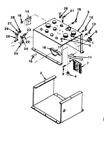
REMOVAL
REMOVE CHASSIS FROM SPECIAL RELAY
ASSEMBLY.
Remove two screw and captive
washer assemblies (1) and
remove chassis (2) from special
relay assembly (3).
REPLACEMENT
REPLACE FAULTY COMPONENT IN SPECIAL
RELAY ASSEMBLY.
a.
Solder/desolder harness wires
as necessary using MIL-STD-454.
b.
Replace faulty potentiometer:
(1) Tag and remove wires from
faulty potentiometer (4).
(2) Remove nut (5) and remove
faulty potentiometer (4).
(3) Install new potentiometer
(4) and secure with nut
(5).
(4) Attach wires to potentio-
meter (4).
6-4