TM5-6115-593-34
NAVFAC P-8-631-34
TO-35C2-3-463-2
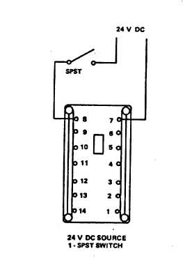
Figure 4-11. Component Assembly Panel, Relay K1 and K50, Test Setup
replaced, carefully solder new
component into place.
(g)
Install relay assembly (18) by
securing brackets (20) to shelf
(21) using screws (19).
(h)
Connect
wires
to
terminal
boards, then remove wire tags.
4-25. TIME DELAY MODULES TD1 AND TD3. Time
delay module TD1 (15, figure 4-10) delays crank limit
relay K19 turn on by 30 seconds. Time delay TD3 (12)
times on and off periods averaging 5-second delays and
controls recrank inhibit relay K6.
a.
Tests for Replaceable Components. Check
the following components on TD1 and TD3:
(1)
Check transistor Q1 (10, figure 4-13
and 16, figure 4-14) by connecting a
transistor tester for current gain of 100
minimum, leakage, or short.
(2)
Check transistors Q2 and Q3 (5 and
4, figure 4-14) by connecting each to
a transistor tester and testing for
current gain of 40 minimum, leakage,
or short.
(3)
Check capacitors (C1 and C2 (6 and
7, figure 4-13) by connecting each to
a capacitor tester and checking for
leakage and capacitance. C1 must
read 10 microfarads, 25 volts ±5
percent.
CR2
must
read
47
microfarads, 50 volts ±10 percent.
(4)
Check capacitor C1 (10, figure 4-14)
by connecting to a capacitor tester
and
checking
for
leakage
and
capacitance. Cl must read 300
microfarads, 30 volts, ±5 percent.
(5)
Check resistors using an ohmmeter
for the following resistance’s:
4-21